
Semi-active vibration absorber control system based on state observation

A state observer and state observation technology, applied in the direction of shock absorber, vibration suppression adjustment, non-rotational vibration suppression, etc., can solve the problem that it is difficult to establish an accurate mathematical model, it is difficult to identify the frequency of vibration signals of rotating machinery, and it is difficult to work, etc. problems, to improve the control effect and system stability, to achieve accurate tracking, and to save costs

Active Publication Date: 2016-05-04
HEFEI UNIV OF TECH
View PDF9 Cites 5 Cited by
  • Summary
  • Abstract
  • Description
  • Claims
  • Application Information

AI Technical Summary

Problems solved by technology

[0006] However, due to the complex working conditions of rotating machinery, the excitation of rotating machinery, including its excitation frequency and excitation amplitude, is always changing, and it is very difficult to accurately identify the frequency of the vibration signal of rotating machinery
On the other hand, since the hysteresis modulus of the magnetorheological elastomer is not only related to the magnitude of the applied magnetic field, but also related to the strain and excitation frequency of the magnetorheological elastomer, the relationship between the hysteresis modulus of the magnetorheological elastomer and the applied magnetic field It is difficult to establish an accurate mathematical model between
Therefore, in the vibration control of the semi-active suspension system of rotating machinery, the existing MRE dynamic shock absorber control algorithm based on excitation frequency identification is difficult to work effectively

Method used


Image

  • Semi-active vibration absorber control system based on state observation
  • Semi-active vibration absorber control system based on state observation
  • Semi-active vibration absorber control system based on state observation

Examples


Embodiment Construction

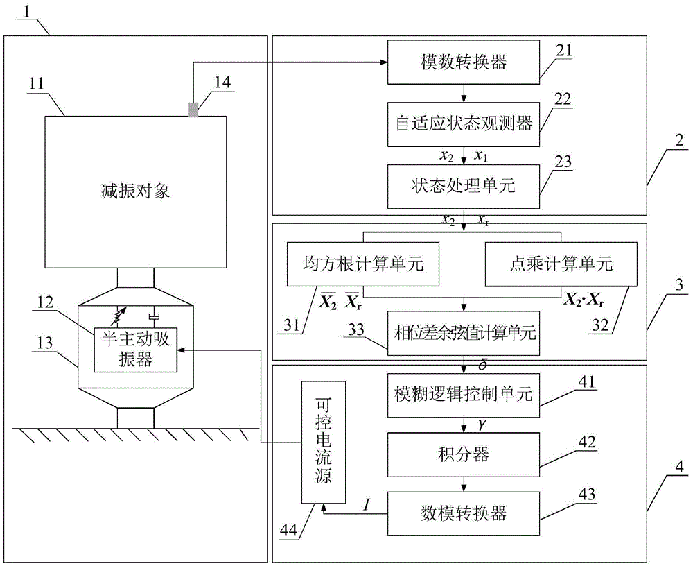
[0036] The composition of the semi-active vibration absorber control system based on state observation in this embodiment includes a semi-active suspension system 1 , a state observation module 2 , a phase difference cosine value calculation module 3 and a current output module 4 .

[0037] like figure 1 As shown, the semi-active suspension system 1 includes a vibration-damping object 11, a semi-active vibration absorber 12, a passive vibration isolator 13, and a sensor 14 installed on the vibration-damping object 11 or the semi-active vibration absorber 12; Perform semi-active vibration-absorbing control on the vibration of the vibration-damping object 11; use the sensor 14 to detect in real time and obtain the analog quantity of the real-time vibration signal corresponding to the output vector of the semi-active suspension system 1; the passive vibration isolator 13 is used to support the vibration-damping object 11.

[0038] The state observation module 2 comprises an anal...


PUM


Abstract

The invention discloses a semi-active vibration absorber control system based on state observation. The semi-active vibration absorber control system is characterized by being composed of a semi-active suspension system, a state observation module, a phase difference cosine value calculation module and a current output module. The semi-active suspension system comprises a vibration reducing object, a semi-active vibration absorber, a passive vibration isolator and a sensor mounted on the vibration reducing object or the semi-active vibration absorber, and is used for detecting vibration information corresponding to the output vector of the semi-active suspension system in real time. The state observation module comprises an analog-digital converter, a self-adaption state observer and a state processing unit, and is used for predicting related vibration information corresponding to the related state vector of the semi-active suspension system in real time. The current output module is composed of a fuzzy logic control unit, an integrator and a controlled current source, and is used for outputting control current needed by the semi-active vibration absorber in real time. The semi-active vibration absorber control system can control vibration of a semi-active vibration absorber system fast, stably and effectively only through one sensor.

Description

technical field [0001] The invention relates to a semi-active vibration absorber control system based on state observation, more specifically, a control system suitable for automobile engine mount systems, new energy vehicle powertrain mount systems, ship power systems, medical equipment systems, and special equipment carrying Magneto-rheological elastomer vibration absorber vibration control system that uses rotating machinery as power for devices, machine tool processing equipment, etc. Background technique [0002] While rotating machinery provides power for engineering applications, it also brings vibration disturbance to the system, and the frequency of vibration disturbance is proportional to its rotational speed. Taking the powertrain of an internal combustion engine as an example, when the internal combustion engine is working, the pitching moment generated by the cylinder pressure and the reciprocating inertial force is the main vibration excitation of the internal ...

Claims


Application Information

Patent Timeline
IPC IPC(8): F16F9/53
CPCF16F9/535
Inventor 白先旭辛付龙钱立军
Owner HEFEI UNIV OF TECH
Learn More