A hydroacoustic cavitation loop reactor

A loop reactor and acoustic cavitation technology, applied in chemical instruments and methods, water pollutants, reflux water treatment, etc., can solve the problems of ultrasonic cavitation application limitations, difficulty in industrialization, and low cavitation intensity, and achieve enhanced The effects of sewage treatment capacity, easy management, and simple technical structure

Inactive Publication Date: 2018-05-08
SHAANXI NORMAL UNIV
View PDF5 Cites 0 Cited by
  • Summary
  • Abstract
  • Description
  • Claims
  • Application Information

AI Technical Summary

Problems solved by technology

[0005] However, although ultrasonic cavitation has high cavitation intensity, only 5% to 10% of the total energy consumption is used for cavitation, and the remaining 90% to 95% of energy is in the form of heat to heat up the system, which makes ultrasonic cavitation The application is greatly limited, it is difficult to achieve industrialization
With the entry of hydraulic cavitation into people's business, we found that hydraulic cavitation has great potential in sewage treatment. Hydronic cavitation technology has more advantages, but hydraulic cavitation has the disadvantage of low cavitation intensity. Therefore, it is particularly important to design a hydroacoustic cavitation circulation device with high ultrasonic cavitation intensity, low energy consumption and high efficiency.

Method used


Image

  • A hydroacoustic cavitation loop reactor
  • A hydroacoustic cavitation loop reactor
  • A hydroacoustic cavitation loop reactor

Examples


Embodiment 1

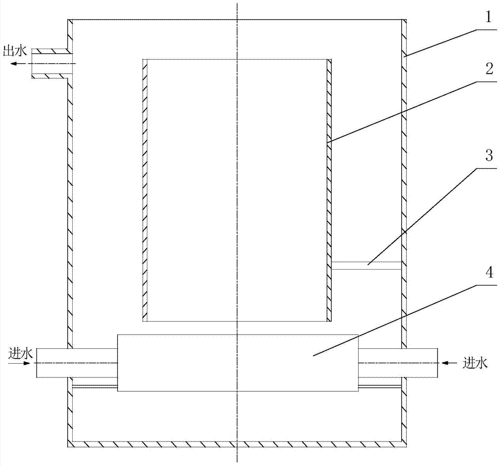
[0022] Depend on figure 1 It can be seen that the hydroacoustic cavitation loop reactor of this embodiment is composed of an outer cylinder 1 , a guide cylinder 2 , a fixed rod 3 and a cavitation nozzle 4 .

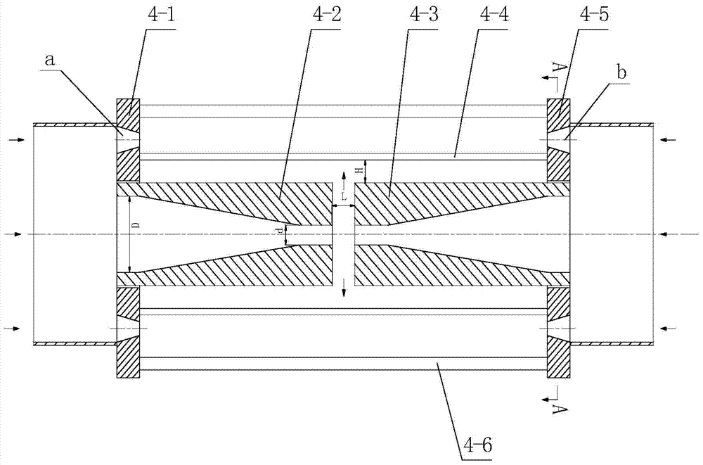
[0023] The outer cylinder 1 of the present embodiment is a cylindrical structure with a diameter of 60 cm. A water outlet is opened on the upper side wall of the outer cylinder 1. The inner cavity of the outer cylinder 1 is 45 cm from the bottom of the outer cylinder 1 through the fixed rod 3 and the outer cylinder 1. The threaded fastener is fixedly installed with a guide tube 2 with a diameter of 50 cm. The central axis of the guide tube 2 coincides with the central axis of the outer tube 1. The rod 3 is fixedly equipped with a cavitation nozzle 4, see figure 2 and 3 , the cavitation spray head 4 of the present embodiment is composed of the first fixed plate 4-1, the first nozzle 4-2, the second nozzle 4-3, the vibrating rod 4-4, the second fixed plate 4-5 and the co...

Embodiment 2

[0027] see Figure 4In this embodiment, a guide tube 2 with a diameter of 46 cm is fixedly installed at a position where the inner cavity of the outer tube 1 is 45 cm from the bottom of the outer tube 1 through a fixed rod 3 and a threaded fastener, and the lower port of the guide tube 2 is outside the The height of the bottom of the tube 1 is 20 cm, and a circular installation hole is processed on the opposite side walls of the bottom of the guide tube 2, and two oppositely arranged joints 5 are respectively threaded on the circular installation holes. Joint 5 is a coaxial annular double-channel structure composed of a central channel and an annular channel. It is a commercially available standard joint. The two joints 5 are connected through the cavitation nozzle 4. The other ends of the joint 5 are connected to 1 The external water inlet pipe is connected.

[0028] The cavitation nozzle 4 of the present embodiment is composed of a first fixed plate 4-1, a first nozzle 4-2,...

Embodiment 3

[0032] In this embodiment, a guide tube 2 with a diameter of 48 cm is fixedly installed in the inner cavity of the outer cylinder 1 through a fixed rod 3 and a threaded fastener. The central axis of the guide tube 2 coincides with the central axis of the outer cylinder 1. A cavitation nozzle 4 is fixedly installed directly below the guide cylinder 2 through a fixed rod 3 welded on the inner wall of the outer cylinder 1 .

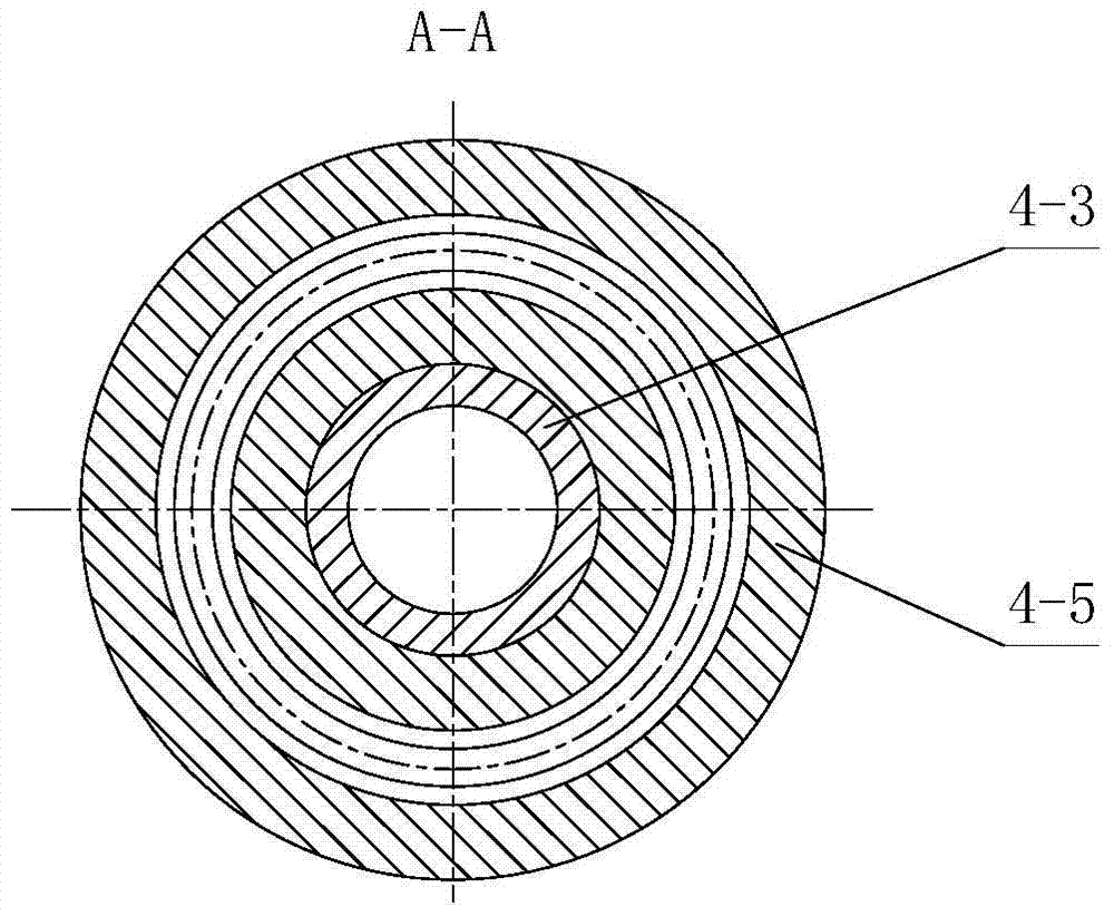
[0033] The cavitation nozzle 4 of the present embodiment is composed of a first fixed plate 4-1, a first nozzle 4-2, a second nozzle 4-3, a vibrating rod 4-4, a second fixed plate 4-5 and a connecting rod 4- 6 components, the first fixed plate 4-1 and the second fixed plate 4-5 are arranged oppositely and connected into an integral structure through three connecting rods 4-6, the first fixed plate 4-1 and the second fixed plate 4-5 The outer wall is fixed to the inner wall of the outer cylinder 1 through the fixing rod 3, and a nozzle installation hole is pr...


PUM

PropertyMeasurementUnit
lengthaaaaaaaaaa
lengthaaaaaaaaaa
diameteraaaaaaaaaa

Abstract

The invention relates to a hydraulic acoustic cavitation circulation flow reactor which comprises an outer shell and a guide shell arranged in the inner cavity of the outer shell, wherein the upper part of the outer shell is provided with a water outlet; a cavitation sprayer communicated with a water inlet pipeline is arranged between the two walls of the lower part or bottom end of the guide shell; and the cavitation sprayer is composed of a first fixed plate, a first nozzle, a second nozzle, a vibrating bar, a second fixed plate and a connecting rod. The synergic effect is generated under the actions of ultrasonic vibration and slit jet so as to generate abundant free radicals, so that the hydraulic cavitation energy consumption of equipment is lowered, the ultrasonic cavitation intensity is greatly enhanced, the sewage treatment capacity is enhanced, the capacity of hydraulic cavitation for degrading organic pollutants is effectively enhanced, the gas-liquid mixing can be enhanced, and the mass transfer and heat transfer effects between gas and liquid are enhanced. The hydraulic acoustic cavitation circulation flow reactor is convenient to operate and easy for management, has the advantages of low cost, simple technical structure and the like, and is suitable for industrialized popularization and application.

Description

technical field [0001] The invention belongs to the technical field of research on cavitation generating devices for liquid fluids, and in particular relates to a hydroacoustic cavitation circulation reactor for treating organic pollutant waste water through enhanced degradation of hydroacoustic cavitation. Background technique [0002] With the growth of population, the continuous development of social economy, the discharge of sewage is increasing day by day, and the problem of water pollution has become an increasingly serious threat to human survival and social development. Preventing the deterioration of water bodies and protecting water resources have become the common pursuit of mankind. The goal. Traditional treatment methods have played and are playing an important role in the prevention and control of water pollution. However, due to the continuous increase in the amount of wastewater, the increasingly complex composition, and the increasingly stringent treatment ...

Claims


Application Information

Patent Timeline
Patent Type & Authority Patents(China)
IPC IPC(8): C02F1/36C02F101/30
CPCC02F1/36C02F2101/30C02F2201/002C02F2301/04
Inventor 沈壮志莫润阳
Owner SHAANXI NORMAL UNIV
Why Eureka
Try Eureka