A method for real-time compensation and correction of rotor magnetic pole position of permanent magnet synchronous motor

A technology for permanent magnet synchronous motors and rotor poles, which is applied in the control of generators, motor generators, AC motors, etc., to achieve the requirements of reduced processing speed, easy implementation, and low dependence

Active Publication Date: 2017-12-29
BEIJING MECHANICAL EQUIP INST
View PDF6 Cites 0 Cited by
  • Summary
  • Abstract
  • Description
  • Claims
  • Application Information

AI Technical Summary

Problems solved by technology

[0004] The purpose of the present invention is to provide a real-time compensation and correction method for the rotor magnetic pole position of a permanent magnet synchronous motor to solve the problem of real-time correction of the rotor magnetic pole position in the closed-loop control of the permanent magnet synchronous motor

Method used


Image

  • A method for real-time compensation and correction of rotor magnetic pole position of permanent magnet synchronous motor
  • A method for real-time compensation and correction of rotor magnetic pole position of permanent magnet synchronous motor
  • A method for real-time compensation and correction of rotor magnetic pole position of permanent magnet synchronous motor

Examples


Embodiment Construction

[0030] A method for real-time compensation and correction of the rotor magnetic pole position of a permanent magnet synchronous motor, the specific steps of which are as follows:

[0031] The first step is to build a real-time compensation and correction platform for the rotor pole position of the permanent magnet synchronous motor

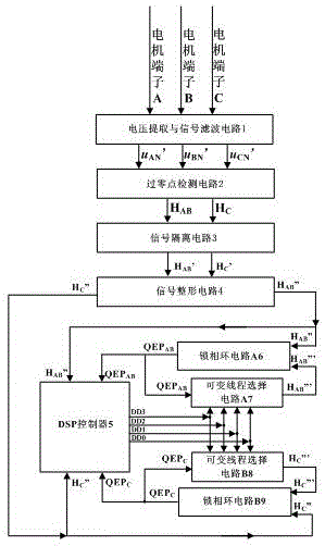
[0032] The permanent magnet synchronous motor rotor pole position real-time compensation and correction platform includes: voltage extraction and signal filter circuit 1, zero-crossing detection circuit 2, signal isolation circuit 3, signal shaping circuit 4, phase-locked loop circuit A6, phase-locked loop circuit B9, DSP Controller 5, variable thread selection circuit A7 and variable thread selection circuit B8.

[0033]The three input terminals of the voltage extraction and signal filtering circuit 1 are respectively connected to the motor terminal A, the motor terminal B, and the motor terminal C, and the three output terminals of the voltage e...


PUM


Abstract

The invention discloses a method for real-time compensation and correction of the rotor magnetic pole position of a permanent magnet synchronous motor. The specific steps are: building a real-time compensation and correction platform for the rotor magnetic pole position of a permanent magnet synchronous motor; a DSP controller (5) for a phase-locked loop circuit A (6 ) and the virtual code disc signal output by the phase-locked loop circuit B (9) carry out frequency division; the DSP controller (5) judges the steering of the motor according to the phase relationship of the two-way orthogonal virtual code disc signals QEPAB and QEPC; the DSP controller ( 5) Obtain the motor speed and delay angle; the DSP controller (5) judges the absolute zero position of the rotor magnetic pole and the position of the rotor magnetic pole. The invention has low dependence on motor parameters and motor mathematical models, and has high detection accuracy; it controls the phase-locked loop circuit and the variable thread selection circuit according to the needs, and changes the frequency of the orthogonal virtual code disc signals QEPAB and QEPC, which is simple and flexible. Easy to implement.

Description

technical field [0001] The invention relates to a method for real-time correction of the rotor magnetic pole position, in particular to a real-time compensation correction method for the rotor magnetic pole position of a permanent magnet synchronous motor. Background technique [0002] Permanent magnet synchronous motors have the advantages of high power density, small rotor moment of inertia, small armature inductance, high operating efficiency, and no slip rings and brushes on the shaft, and are widely used in high-performance motion control fields in the small and medium power range, such as robots , CNC machine tools and other applications. With the development of power electronics technology and motor control theory, the closed-loop control method of high-performance permanent magnet synchronous motor represented by vector control has been developed rapidly and widely used, and the quality of the permanent magnet synchronous motor control method depends on the rotor mag...

Claims


Application Information

Patent Timeline
Patent Type & Authority Patents(China)
IPC IPC(8): H02P21/18H02P25/022
Inventor 崔臣君何成峰张文波王利
Owner BEIJING MECHANICAL EQUIP INST
Why Eureka
Try Eureka