Occluder and method of making the same
A production method and technology of occluder, which is applied in medical science, surgery, prosthesis, etc., can solve the problems of aggravating the difficulty and risk of surgery, large volume of occluder, and difficulty in adapting to blood vessels, so as to reduce the difficulty and volume of surgery Small, effect of reducing surgical risk
- Summary
- Abstract
- Description
- Claims
- Application Information
AI Technical Summary
Problems solved by technology
Method used
Image
Examples
Embodiment 1
[0100] First, if Figure 13 as well as Figure 14 As shown, on the mold rod 12, adopt two groups of grid lines to cross weave to form the network pipe 13, wherein the network pipe 13 includes the network pipe middle part 131 for forming the waist 3, and is used to form two disc structures (the first one) respectively. The network pipe end 132 of the disk-shaped structure 201 and the second disk-shaped structure 206).
[0101] It can be understood that the mold rod 12 in this embodiment has a shape that is thinner in the middle and thicker at the two ends, so cross-braiding grid lines on the mold rod 12 can form the network pipe end 132 with a larger diameter and the middle part of the network pipe with a smaller diameter. 131. In addition, because the surface of the middle part of the mold rod 12 is smooth, the diameter of the formed mesh pipe middle part 131 is consistent in the length direction.
[0102] Next, the mold stick 12 and the mesh pipe 13 sleeved on the mold sti...
Embodiment 2
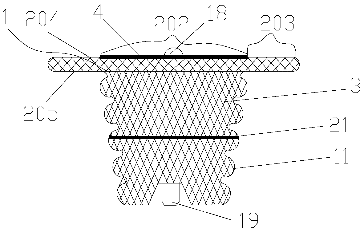
[0115] The manufacturing method of the occluder provided by this embodiment is substantially the same as that of the first embodiment, except that the folds 11 are formed.
[0116] Such as Figure 21 As shown, in the present embodiment, the pleat forming die 15 is also used to make the middle part of the network tube form 131 into a pleat 11. The pleat forming die 15 also includes a fixed thick rod 151, a thin rod 152, and a movable thick rod 153; one end of the thin rod 152 is connected to the fixed One end of the thick rod 151 is fixedly connected to the disc surface, and the other end of the thin rod 152 is slidably passed through the movable thick rod 153 . The difference is that in this embodiment, the surface of the thin rod 152 in the pleat forming mold 15 is provided with several wavy or zigzag structures arranged in sequence along the axial direction, and the wavy or zigzag structures are arranged on the surface of the thin rod 152 in a ring shape.
[0117] When form...
Embodiment 3
[0121] The difference between the manufacturing method of the occluder provided in this embodiment and the first embodiment is that in this embodiment, the waist 3 with the folds 11 and the mesh frame 20 with the preset expanded shape are formed in one process step.
[0122] Specifically, in this embodiment, first, as Figure 23 On the mold bar, adopt the grid line cross braiding mode to form the network pipe 13 and heat setting, wherein, the network pipe 13 includes the network pipe middle part 131 for forming the waist 3, and is used to form two disc structures (the first disc structure) respectively. 201 and the network pipe end 132 of the second disk-shaped structure 206). The difference from the first embodiment is that in this embodiment, the mold stick is cylindrical with the same diameter, and the net tube 13 is formed by weaving on the mold stick 12, and the diameter of the middle part of the net tube and the end of the net tube are the same.
[0123] After that, if ...
PUM
 Abstract
Description
Claims
Application Information
 - Generate Ideas
- Intellectual Property
- Life Sciences
- Materials
- Tech Scout
- Unparalleled Data Quality
- Higher Quality Content
- 60% Fewer Hallucinations
Browse by: Latest US Patents, China's latest patents, Technical Efficacy Thesaurus, Application Domain, Technology Topic, Popular Technical Reports.
© 2025 PatSnap. All rights reserved.Legal|Privacy policy|Modern Slavery Act Transparency Statement|Sitemap|About US| Contact US: help@patsnap.com


