
Clamping assisting mechanism for tool grinder

A tool grinder and auxiliary mechanism technology, which is applied in the direction of manufacturing tools, other manufacturing equipment/tools, grinding workpiece supports, etc., can solve the problem of not effectively ensuring the radial runout away from the clamp spring, reducing the clamping rigidity of the elastic clamp spring, cutting tools, etc. Large radial runout and other problems, to achieve the effect of simple structure, improved machining accuracy, and high clamping accuracy

Inactive Publication Date: 2016-03-30
TAIZHOU BEIPING MASCH TOOL CO LTD
View PDF7 Cites 12 Cited by
  • Summary
  • Abstract
  • Description
  • Claims
  • Application Information

AI Technical Summary

Problems solved by technology

The round bar tool has a large length-to-diameter ratio. The structure of the tool determines that there is a large cutting allowance when machining the tool. At the same time, due to the technical parameters of the tool and the interference of the grinding wheel when processing the tool, the clamping capacity of the elastic clip spring is reduced. Rigidity, because the grinding part of the workpiece is far away from the clamping part of the elastic clip spring, the radial runout of the tool becomes larger, the grinding rigidity is poor, and the scrap rate is high
[0004] In China, in order to improve the grinding rigidity of the tool away from the clamping part, a common measure is to install a fixed auxiliary support away from the elastic clip spring. This support can only be adjusted horizontally and vertically. The accuracy of the support It is difficult to ensure that it is only suitable for rough adjustment. For tools with high precision requirements, the radial runout away from the clamp spring cannot be effectively guaranteed, and this fixed auxiliary support is only suitable for manual workpiece loading and unloading

Method used


Image

  • Clamping assisting mechanism for tool grinder
  • Clamping assisting mechanism for tool grinder
  • Clamping assisting mechanism for tool grinder

Examples


Embodiment Construction

[0030] The following are specific embodiments of the present invention and in conjunction with the accompanying drawings, the technical solutions of the present invention are further described, but the present invention is not limited to these embodiments.

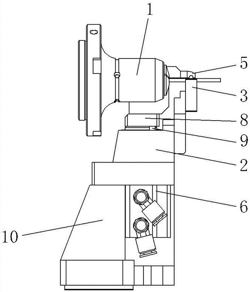
[0031] Such as figure 1 The clamping auxiliary mechanism of the tool grinder shown is located at the collet 1 of the tool grinder, including a support 2 and a V-shaped block 3 that can be manually adjusted up and down on the support 2, and the V-shaped block 1 The top of 3 has a V-shaped groove extending along the axis of collet 1. Such as figure 2 As shown, the support one 2 is provided with the support two 4 located at the side of the workpiece, the support two 4 has a horizontal pressing plate 5 extending to the top of the V-shaped groove one, and the extending direction of the pressing plate 5 is perpendicular to the axis of the workpiece. The support one 2 is also provided with a drive unit one 6 for driving the su...


PUM


Abstract

The invention provides a clamping assisting mechanism for a tool grinder, and belongs to the technical field of machinery. The problem that a conventional clamping assisting mechanism for the tool grinder can only perform movement and adjustment in a horizontal direction and a perpendicular direction, so that the supporting precision is difficult to guarantee is solved. The mechanism comprises a supporting seat I and a V-shaped block I arranged on the supporting seat I, wherein a V-shaped slot I is formed in the top of the V-shaped block; a supporting seat II is arranged on the supporting seat I, a pressing plate is arranged on the supporting seat II, and a driving unit I is also arranged on the supporting seat I; the mechanism further comprises a fixing seat II, wherein a supporting seat III is arranged on the fixing seat II, a regulating assembly is arranged on the supporting seat III, a V-shaped block II is arranged on the regulating assembly, a V-shaped slot II is formed in the V-shaped block II, and a driving unit II is arranged on the fixing seat II. According to the clamping assisting mechanism disclosed by the invention, the rigidity of a collet is improved through the pressing plate and the V-shaped block I at a near clamping end, the grinding rigidity and the grinding precision during the grinding of a cutter are improved through the V-shaped block II at a far clamping end, and the clamping assisting mechanism has the advantages that the clamping precision is high, and the processing precision and the stability of the tool grinder can be effectively guaranteed.

Description

technical field [0001] The invention belongs to the technical field of machinery, and relates to a clamping auxiliary mechanism, in particular to a clamping auxiliary mechanism of a tool grinder. Background technique [0002] At present, with the continuous emergence of new technologies and materials, product processing tends to be more and more high-precision and good surface finish. Excellent products are an important guarantee for enterprises to improve product added value and competitiveness. High-quality high-precision tools occupy 60% of the domestic high-end market. High-precision tools are a necessary condition for processing high-precision parts, and high-precision tools are processed by high-precision CNC tool grinders. High-precision CNC tool grinding machines are mainly used for processing various thread tools, various hole processing tools and various hard and super carbide tools. Using a grinding wheel to shape the tool at one time is an effective means for th...

Claims


Application Information

Patent Timeline
Patent Type & Authority Applications(China)
IPC IPC(8): B24B41/06B24B3/00B24B3/18
CPCB24B41/06B24B3/00B24B3/18
Inventor 虞荣华
Owner TAIZHOU BEIPING MASCH TOOL CO LTD
Learn More