
A non-bonded rib ring anchor sealing system and its installation and construction method

A construction method and non-bonding technology, applied in the direction of structural elements, building components, building reinforcements, etc., can solve the problems of limited compression of rubber pads, low reliability, oil leakage, etc. Good effect, convenient sealing effect

Active Publication Date: 2017-11-28
LIUZHOU OVM MASCH CO LTD
View PDF1 Cites 0 Cited by
  • Summary
  • Abstract
  • Description
  • Claims
  • Application Information

AI Technical Summary

Problems solved by technology

At present, the sealing methods of the unbonded rib ring anchor system are as follows: Figure 18 , each exposed unbonded tendon is sealed by using the rubber pad on the end face and a sealing sleeve. Since the clips are higher than the end face of the anchor plate, the gap between each pair of clips is relatively large, and the grease without bonding ribs is easy to overflow through the gap between the clips. Although there is a rubber pad as a transitional seal on the end face of the anchor plate, the compression of the entire rubber pad is limited, and it cannot be effectively sealed to ensure that the grease does not leak, and the reliability is not high. Oil leakage has already occurred in the application project; the patent announcement number is CN201033913Y "No Anticorrosion Device for Bonded Rib Ring Anchor and Anchor Head" discloses an integral sealing device, which uses the upper and lower half boxes plus two end cover plates or the cavity closed by the left and right half boxes, and epoxy resin or polyurethane is poured into the cavity to achieve The disadvantage of this device is that the protective cover in the patent occupies too much space in the notch, and more anticorrosion substances need to be poured. The strength of the anticorrosion substance is low, far less than the strength of concrete, which affects the overall strength of the notch area, and the anticorrosion of the perfusion The substance will be bonded and fixed with the working clip, which will affect the anchoring performance

Method used


Image

  • A non-bonded rib ring anchor sealing system and its installation and construction method
  • A non-bonded rib ring anchor sealing system and its installation and construction method
  • A non-bonded rib ring anchor sealing system and its installation and construction method

Examples


Embodiment 1

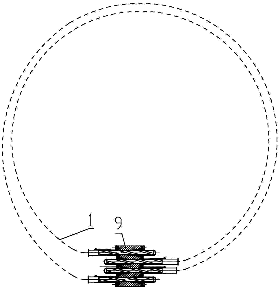
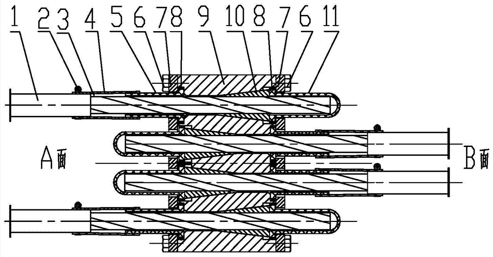
[0065] A non-bonded rib ring anchor sealing system, including an anchor plate 9 for anchoring the non-bonded rib 1, a clip 10, and the head and tail ends of the non-bonded rib 1 are respectively anchored on the A surface and the B side of the anchor plate 9 surface (see figure 1 );

[0066] The non-bonded rib ring anchor sealing system also includes a transition pipe 4, a sealing connection pipe 5, a bolt 6, a pressure plate 7, and a sealing ring 8. There are anchor plate counterbore 91 and a stepped hole at the large end of the tapered hole and the straight hole end of the anchor plate 9 respectively. 92 (see image 3 );

[0067] In the installed state, the locking ring 2, the transition pipe 4, the pressure plate 7, and the sealing connecting pipe 5 equipped with the sealing ring 8 are sequentially set on the non-adhesive rib 1, and the non-adhesive rib 1 penetrates into the corresponding hole of the anchor plate. After the tension of the clip is finished, the end surfac...

Embodiment 2

[0069] A non-adhesive tendon ring anchor sealing system, the basic structure of which is the same as that of Embodiment 1. The difference from Embodiment 1 is that the clip end does not use a sealing sleeve 11, but uses a sealing cover 12, a transition pipe 4 and a sealing connection pipe 5 Replace the sealing sleeve 11 to realize the sealing without bonding ribs at the clip end (see Figure 5 ).

Embodiment 3

[0071] A non-bonded rib ring anchor sealing system, its basic structure is the same as that of Embodiment 1 or Embodiment 2, and the difference from Embodiment 1 or Embodiment 2 is that: between the sealing sleeve 11 or the sealing connecting pipe 5 and the pressure plate 7 There is a spring washer 13, after the pressure plate 7 is fixed, the pressure plate 7 can provide the sealing force to the sealing sleeve 11 or the sealing connecting pipe 5, and tighten the clip through the sealing sleeve 11 or the sealing connecting pipe 5 (see Figure 6 , Figure 6 Shown is the sealing connection pipe 5, and the sealing sleeve 11 has a similar structure, not shown), so that its anti-loosening performance is better.


PUM


Abstract

An unbounded bar circular anchor sealing system comprises anchor plates used for anchoring unbounded bars, clamping pieces, transition tubes, tight coupling tubes, bolts, pressing plates and sealing rings, wherein step holes are formed in the large taper hole end and the straight hole end of each anchoring plate respectively, and each unbounded bar is sleeved with a corresponding locking ring, the corresponding transition tube, the corresponding pressing plate, and the corresponding tight coupling tube provided with the corresponding sealing ring in sequence in the installation state; each unbounded bar extends into a corresponding hole of the corresponding anchoring plate, the end face of each clamping piece sinks to the position below the end face of the corresponding anchoring plate after being completely tensioned, each pressing plate tightly presses the corresponding tight coupling tube through the corresponding bolt, each sealing ring is matched with a counter bore of the corresponding anchoring plate, and each clamping piece end is arranged in a sealing sleeve to achieve clamping piece end radial seal; the small end of corresponding tight coupling tube is of a conical structure and in expanding fit with the corresponding transition tube in a sealed mode; each unbounded bar with a PE tube stripped off as the requirement of tensioning construction is held by the corresponding transition tube, each transition tube is then in lap joint with the PE tube of the corresponding unbounded bar and locked by the corresponding locking ring, and an unbounded bar and clamping and anchoring unit fully-independent sealed structure is formed by each unbounded bar. The installation and construction method is simple, and construction efficiency can be improved greatly.

Description

technical field [0001] The invention relates to a prestressed construction machine tool and its installation and construction method, in particular to a non-adhesive rib ring anchor sealing system and its installation and construction method. Background technique [0002] The non-bonded tendon ring anchor system requires full sealing of the non-bonded tendons and the clamping anchor unit. One is to ensure the anti-corrosion requirements of the prestressed tendons under high stress conditions and reliable long-term anchoring performance. The other is to prevent grease from leaking out, causing Environmental pollution, especially in water conservancy projects, will directly affect water quality. At present, the sealing methods of the unbonded rib ring anchor system are as follows: Figure 18 , each exposed unbonded tendon is sealed by using the rubber pad on the end face and a sealing sleeve. Since the clips are higher than the end face of the anchor plate, the gap between eac...

Claims


Application Information

Patent Timeline
Patent Type & Authority Patents(China)
IPC IPC(8): E04C5/12
CPCE04C5/12
Inventor 莫鲤木蒋业东黄颖温朝臣李军左海宁刘进经凤明
Owner LIUZHOU OVM MASCH CO LTD
Learn More