Liquid filtering method and filtering device
A filtration device and filtration method technology, applied in the direction of filtration separation, membrane filter, separation method, etc., can solve the problems of unsatisfactory continuous filtration, high investment and operation costs, complicated operation and maintenance, etc., to reduce the probability of water film formation, Low investment and operating costs, high filtration accuracy
- Summary
- Abstract
- Description
- Claims
- Application Information
AI Technical Summary
Problems solved by technology
Method used
Image
Examples
Embodiment 1
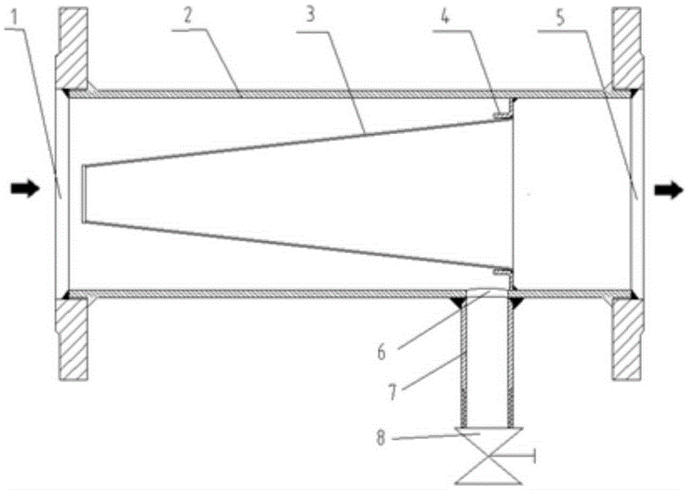
[0026] Refer to attached figure 1 It can be seen that the liquid filter device of the present invention includes a device body 2 and a filter body 3 inside the device body 2 .
[0027] The device body 2 is a cylindrical pipe structure, which is horizontally arranged, one end of which is a liquid inlet 1, and the other end is a liquid outlet 5. The filter body 3 is a conical filter, such as a cone without a lower surface. The body or the upper part is a conical frustum structure of a platform. The open end of the conical filter screen is sealed and fixedly connected to the inner wall of the cylindrical pipe through the support frame 4. side, and the inner side of the cone is the liquid outlet side.
[0028] A dirt collection chamber is formed between the tapered outer wall of the filter body 3 and the inner wall of the device body 2 for collecting solid impurities filtered out by the filter body 3 . In order to facilitate the discharge of impurities in the sewage collection c...
Embodiment 2
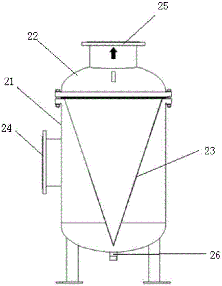
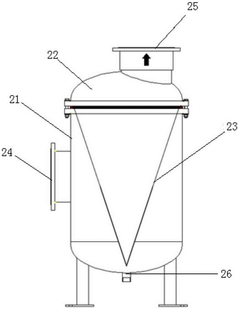
[0032] Refer to attached figure 2 As shown, the difference between this embodiment and Embodiment 1 is that the equipment body is a cylindrical tank structure, which includes a tank body 21 and a cover body 22, and the filter body 23 is in the shape of an inverted cone or an inverted cone The platform structure is arranged inside the equipment body, and the preferred solution is: the connection between the filter body 23 and the equipment body is set at the connection between the tank body 21 and the cover body 22, the liquid inlet 24 is set on the side wall of the tank body 21, and the sewage discharge The port 26 is arranged at the bottom of the tank body 21 , and the liquid outlet 25 is arranged at the center of the cover body 22 , that is, the center line of the liquid outlet 25 coincides with the central axis of the tank body 21 . Certainly, the centerline of liquid outlet 25 also can not coincide with the central axis of tank body 21, as attached image 3 shown. All t...
Embodiment 3
[0034] Refer to attached Figure 4 As shown, the difference between the third embodiment and the second embodiment is that the opening end of the inverted cone or inverted cone-shaped platform structure of the filter body 33 is an inclined surface, which is obliquely arranged on the inner wall of the tank body 31, and the liquid outlet 35 is arranged On the side wall of the tank body 31 on the liquid outlet side, it communicates with the cavity surrounded by the inner wall of the filter body 33 and the tank body 31 , and the sewage outlet 36 is arranged at the bottom of the tank body 31 . The rest of the structure is the same as that of the second embodiment above, and will not be described here.
[0035] The liquid filtering method of the present invention is as follows: the liquid to be filtered is filtered from the outside to the inside of the conical filter, that is, flows into the device body from the liquid inlet, and the liquid filtered by the conical filter flows out f...
PUM
 Abstract
Description
Claims
Application Information
 - R&D
- Intellectual Property
- Life Sciences
- Materials
- Tech Scout
- Unparalleled Data Quality
- Higher Quality Content
- 60% Fewer Hallucinations
Browse by: Latest US Patents, China's latest patents, Technical Efficacy Thesaurus, Application Domain, Technology Topic, Popular Technical Reports.
© 2025 PatSnap. All rights reserved.Legal|Privacy policy|Modern Slavery Act Transparency Statement|Sitemap|About US| Contact US: help@patsnap.com


