Vehicle speed control mechanism for bullet loading vehicle

A technology for vehicle speed control and vehicle use, which is applied to the layout of power plant control mechanisms, vehicle components, transportation and packaging, etc. It can solve problems such as poor driving stability, body vibration, poor ride comfort, etc., achieve a high degree of automation, and solve the sense of frustration Strong, easy-to-operate effect

Active Publication Date: 2016-03-16
贵州航天特种车有限责任公司
View PDF5 Cites 3 Cited by
  • Summary
  • Abstract
  • Description
  • Claims
  • Application Information

AI Technical Summary

Problems solved by technology

[0003] The present invention aims to provide a vehicle speed control mechanism for a loading vehicle to solve the problems of vehicle body shaking, walking jerky, poor driving stability, and poor ride comfort in traditional self-propelled external weapon loading vehicles.

Method used


Image

  • Vehicle speed control mechanism for bullet loading vehicle
  • Vehicle speed control mechanism for bullet loading vehicle

Examples


Embodiment Construction

[0017] The technical scheme of the present invention will be further described below in conjunction with the accompanying drawings, but the required protection scope is not limited to the description;

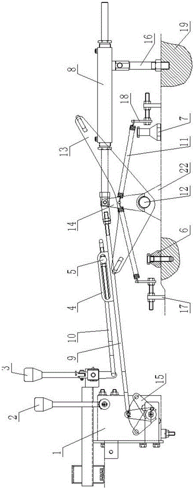
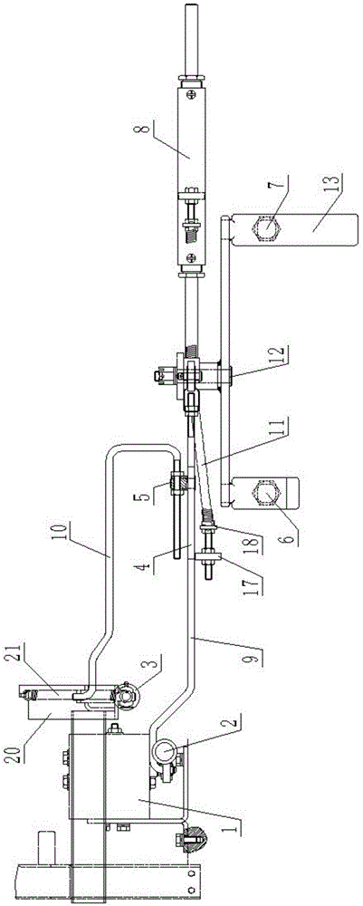
[0018] Such as Figure 1-2 As shown, the speed control mechanism for a loading vehicle provided by the present invention includes a pedal 13, the middle part of the top end of the pedal 13 is hinged on the pedal seat 22 through the pedal shaft 12, the pedal seat 22 is fixed on the vehicle frame 19, and the middle part of the pedal shaft 12 is fixed There is a vertically arranged swing arm 14, the top of the swing arm 14 is hinged with a drive rod 9, the other end of the drive rod 9 is hinged on the lever 15 outside the throttle controller 1, and the drive rod 9 is fixed with a vertically arranged speed limiter. Slot plate 4; the accelerator controller 1 is provided with a brake handle 2 and a cover plate 20, the front end of the cover plate 20 is hinged to the speed-limiting ha...


PUM


Abstract

The invention discloses a vehicle speed control mechanism for a bullet loading vehicle. The vehicle speed control mechanism comprises a pedal; the middle of the top end of the pedal is hinged to a pedal base through a pedal shaft; the pedal base is fixed on a frame; a vertical swing arm is fixedly connected to the middle of the pedal shaft; a driving rod is hinged to the top end of the swing arm; the other end of the driving rod is hinged to a shift rod outside a throttle controller; a vertical speed limiting slotted board is fixedly connected onto the driving rod; a brake handle and a cover plate are arranged on the throttle controller; a speed limiting handle is hinged to the front end of the cover plate; a speed limiting pull rod is hinged to the bottom end of the speed limiting handle; a rotating shaft perpendicular to the speed limiting pull rod is fixedly connected to the right end of the speed limiting pull rod; and the front end of the rotating shaft is inserted in a sliding chute in the middle of the speed limiting slotted board. The vehicle speed control mechanism solves the problem that a conventional bullet loading vehicle is poor in running continuity, poor in form stability, and poor in smoothness, and has the advantages of being high in degree of automation, convenient to operate, and convenient and fast to maintain.

Description

technical field [0001] The invention relates to a vehicle speed control mechanism, in particular to a vehicle speed control mechanism for a loaded vehicle. Background technique [0002] At present, for the replacement of external weapons of fighter jets, there is a special replacement vehicle called a self-propelled external weapon loading vehicle. Its main function is to complete the lifting and replacement of external weapons after positioning, which requires this self-propelled external weapon The weapon loading vehicle has the functions of autonomous walking, lifting, braking and positioning at the same time. The self-propelled external weapon loading vehicle used today cannot meet the requirements, which is mainly reflected in the difficulty of speed control during autonomous walking. This is because It is required that the self-propelled external weapon loading vehicle can run at a high speed not greater than 20Km / h, a low speed not greater than 3Km / h, and run at a sta...

Claims


Application Information

Patent Timeline
Patent Type & Authority Applications(China)
IPC IPC(8): B60K26/02
Inventor 谌洪兴张忠荣吕华简中强牛新民
Owner 贵州航天特种车有限责任公司
Why Eureka
Try Eureka