
Circumferential scanning imaging control method and circumferential scanning imaging system

A technology of cycle-scanning imaging and control methods, which is applied in radiation pyrometry, measuring devices, instruments, etc., can solve the problems of low indication accuracy and achieve the effects of clear imaging, simple control, and difficult to control errors

Inactive Publication Date: 2016-03-02
LUOYANG INST OF ELECTRO OPTICAL EQUIP OF AVIC
View PDF6 Cites 20 Cited by
  • Summary
  • Abstract
  • Description
  • Claims
  • Application Information

AI Technical Summary

Problems solved by technology

[0003] The purpose of the present invention is to provide a control method for scanning imaging and a scanning imaging system to solve the problem of low precision of target orientation caused by the high-speed movement of the detector.

Method used


Image

  • Circumferential scanning imaging control method and circumferential scanning imaging system
  • Circumferential scanning imaging control method and circumferential scanning imaging system
  • Circumferential scanning imaging control method and circumferential scanning imaging system

Examples


Embodiment Construction

[0029] The present invention will be described in further detail below in conjunction with the accompanying drawings.

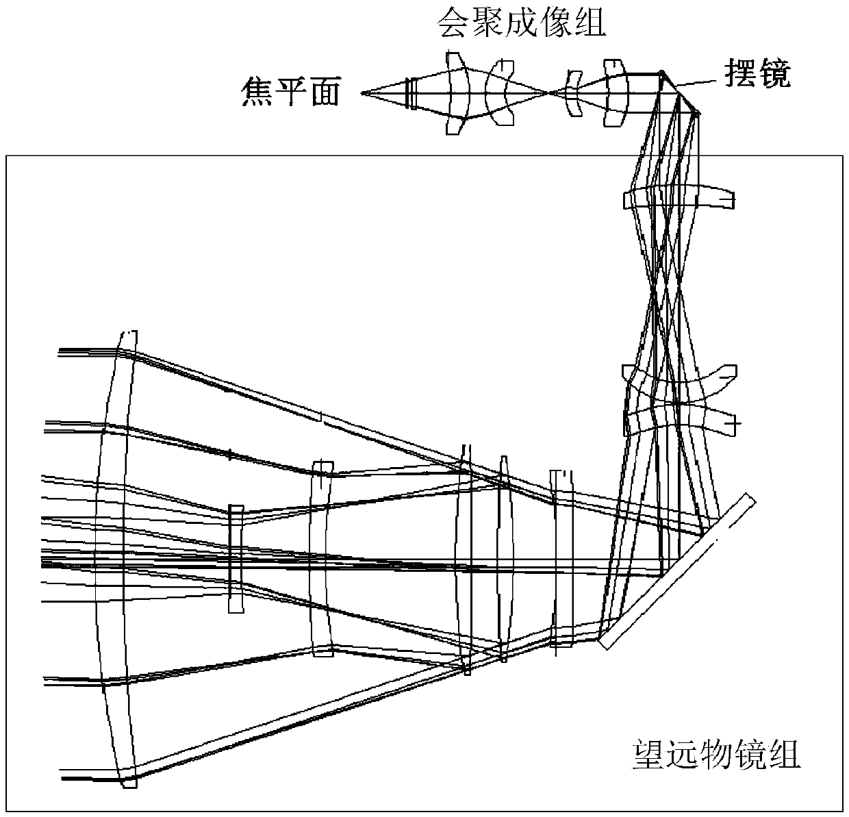
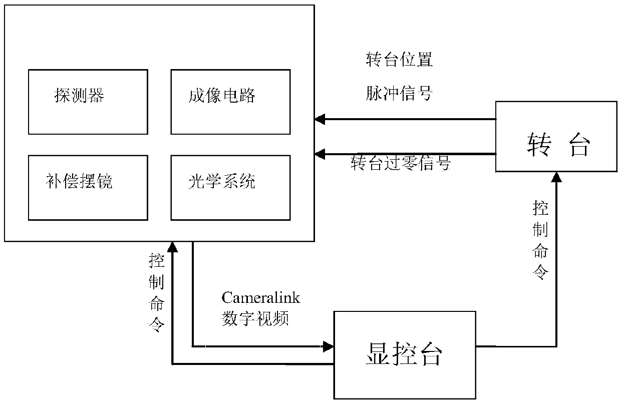
[0030] like figure 1 The cycle scanning imaging system shown includes an azimuth scanning turntable on which an infrared optical system, a detector and an azimuth compensation swing mirror are fixed. Among them, the infrared optical system includes the telescopic objective lens group and the converging imaging group. The telescopic objective lens group, the azimuth compensation swing mirror, the converging imaging group and the detector are arranged in sequence from the object side to the image side on the same optical axis, and the light from the object side passes through the The telescopic objective lens group, the azimuth compensation swing mirror, and the converging imaging group are finally imaged on the focal plane on the detector.

[0031] The azimuth scanning turntable adopts a two-axis turntable, which can realize uniform horizontal scanning and up...


PUM


Abstract

The invention relates to a circumferential scanning imaging control method and a circumferential scanning imaging system. A circumferential scanning imaging system which the method is based on comprises an orientation scanning rotary table, and an infrared optical system, a detector and an orientation compensation oscillating mirror which are fixedly arranged on the orientation scanning rotary table, a view field offset generated every time when the orientation compensation oscillating mirror swings is used for compensating a view field angle corresponding to successive imaging, and when an imaging view field is fixed, a swinging angular speed needed by the orientation compensation oscillating mirror is alpha / T<INT>, wherein alpha is an angle which the oscillating mirror needs to swing for compensating the view field, and T<INT> is integration time of exposure of the detector, needing to be met when the orientation compensation oscillating mirror swings an angle of alpha. In circumferential scanning control, the swinging angular speed of the oscillating mirror has nothing to do with the rotating speed of the rotary table, and since the swinging angular speed of the oscillating mirror is not affected by the rotating speed of the rotary table, the control method is simple to control, is not prone to control errors and realizes non-trailing coupling.

Description

technical field [0001] The invention relates to a control method and a scan imaging system of a scan imaging, belonging to the scan imaging field of an infrared detector. Background technique [0002] At present, most infrared scanning imaging systems are based on infrared column detectors. It is very difficult to change the scanning speed in real time, and usually do not have tracking and searching functions. In recent years, the research on the infrared scanning imaging system based on the area array detector has been carried out in China. The research shows that the use of the area array detector further improves the image signal-to-noise ratio and the observation distance compared with the line array detector, and it is easy to realize tracking and searching. However, due to the high-speed motion of the detector cycle, the target is trailed, resulting in low accuracy of target orientation indication, and because the image is blurred, it is difficult to observe the enviro...

Claims


Application Information

Patent Timeline
Patent Type & Authority Applications(China)
IPC IPC(8): G01J5/00G02B26/08G02B26/10G02B27/00
Inventor 杨逸柳王凯孙小亮
Owner LUOYANG INST OF ELECTRO OPTICAL EQUIP OF AVIC
Learn More