Annular direct-injection burner cap for burner and tool

A burner and annular cover plate technology, applied in the direction of burners, gas fuel burners, combustion methods, etc., can solve the problems of low thermal efficiency, insufficient mixing, temperature rise, etc., to achieve improved thermal efficiency and high production quality Effect

Active Publication Date: 2016-02-24
GUANGDONG USATON ELECTRIC CO LTD
View PDF5 Cites 0 Cited by
  • Summary
  • Abstract
  • Description
  • Claims
  • Application Information

AI Technical Summary

Problems solved by technology

[0002] At present, the high efficiency, environmental protection and easy processing of gas appliances are the development and pursuit of the industry, but the fire cover for the burner generally has secondary air supplementation, insufficient mixing, and high temperature, resulting in low thermal efficiency and excessive CO content in the flue gas. High, especially NOX, an important indicator of environmental protection, fails to meet the requirements of environmental protection and energy-saving products; at the same time, due to the large number of fire holes in the fire cover, each fire hole must be processed one by one, and the production efficiency and production quality are low.

Method used


Image

  • Annular direct-injection burner cap for burner and tool
  • Annular direct-injection burner cap for burner and tool
  • Annular direct-injection burner cap for burner and tool

Examples


Embodiment 1

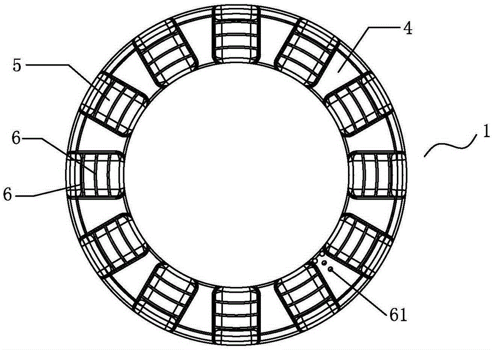
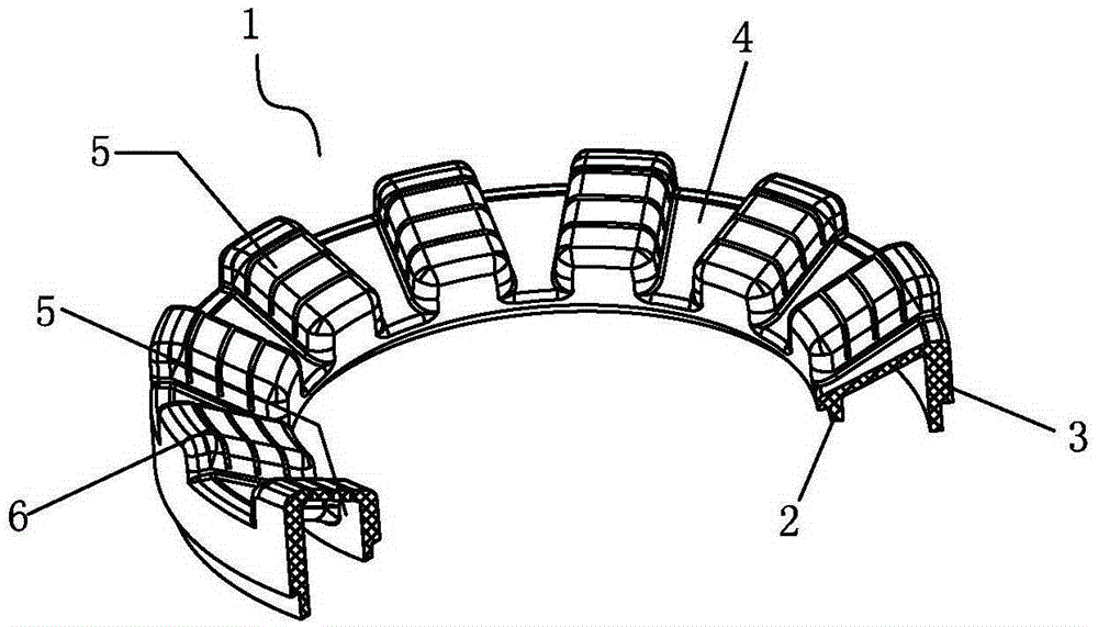
[0026] Such as figure 1 , figure 2 As shown, a direct-injection annular fire cover for a burner includes a fire cover body 1 , and the fire cover body 1 includes an inner ring wall plate 2 , an outer ring wall plate 3 and a circular top cover 4 . The annular cover plate 4 is in the shape of an inverted truncated cone, and there are several hollow premixing chambers 5 that open downward on the annular cover plate 4, and the length direction of the premixing chamber 5 is along the busbar direction of the annular cover plate 4 ;

[0027] There are combustion holes 6 on the premix chamber 5 .

[0028] The combustion holes 6 are arc-shaped, and several combustion holes are distributed on concentric circles with different diameters;

[0029] Adjacent combustion holes on two adjacent premix chambers 5 are on a circle.

[0030] The present invention can also be realized in the following way: the combustion hole 6 is in a spiral shape, there are several combustion holes on the pre...

Embodiment 2

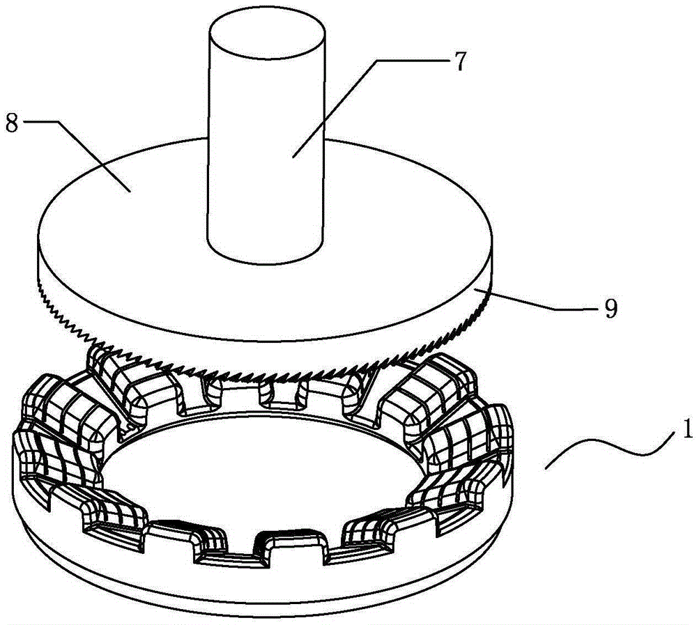
[0033] Such as image 3 , Figure 4 Shown, a kind of cutting tool, it comprises driving shaft 7, base 8 and at least two cutting knives 9;

[0034] The cutting knife 9 includes a cylindrical seat 91 and several cutter bodies 92 provided with the ends of the cylindrical seat;

[0035] One end of the drive shaft 7 is fixedly connected to the base 7, and the cylindrical seat 91 of the cutter is fixedly connected to the base 8;

[0036] The length of the cylindrical seat 91 decreases gradually from the radially inner side to the radially outer side of the base 8 of the cutting blade 9 .

[0037] During use, the fire cover body 1 moves along a straight line, and the drive shaft 7 drives the cutting knife 9 to rotate, and the process can be completed.

Embodiment 3

[0039] Such as Figure 5 , Figure 6 Shown, a kind of cutter, it comprises base 8 and at least two cutting blades 9; Cutting blade 9 is circular arc; Cutting blade 9 is arranged on one end of base 8, and the other end of base 8 is a fixed end;

[0040] The cutting knives 9 are distributed in the form of concentric circles of different diameters;

[0041] The cutting blade 9 takes the fixed end of the base 8 as the center of a circle, and the height from the cutting edge to the base 8 gradually decreases from the radially inner side to the radially outer side.

[0042] When the present invention is in use, as Figure 6 As shown, the fire cover body 1 rotates, and the cutter moves forward along a straight line, which can be completed.


PUM


Abstract

An annular direct-injection burner cap for a burner comprises a burner cap body. The burner cap body comprises an inner annular wallboard, an outer annular wallboard and a circular top cover. The circular top cover is in an inverted circular-truncated-cone shape and provided with multiple hollow premixing cavities with downward openings. The length direction of the premixing cavities is in the generatrix direction of the circular top cover. The premixing cavities are provided with burning holes. A tool comprises a drive shaft, a base and a tool body. By the adoption of the structure, high efficiency and environmental friendliness are achieved; sufficient air mixing and supplementing is achieved through suspended fire outlet holes, sufficient burning in direct injection is achieved, the temperature of the burner cap is lowered, heat efficiency is improved and reaches energy efficiency exceeding first level, and the NOX content in smoke is lowered effectively and meets the environmental requirement; production efficiency is high, and production quality is high; and the defect that each fire hole in a burner cap in the market is machined once is overcome, the manner in which tens of or hundreds of fire holes need to be machined tens of or hundreds of times is changed into the manner in which machining only needs to be conducted once, production efficiency and production quality are improved greatly.

Description

technical field [0001] The invention relates to a cooker burner device, in particular to an annular fire cover of the burner. Background technique [0002] At present, the high efficiency, environmental protection and easy processing of gas appliances are the development and pursuit of the industry, but the fire cover for the burner generally has secondary air supplementation, insufficient mixing, and high temperature, resulting in low thermal efficiency and excessive CO content in the flue gas. High, especially NOX, an important indicator of environmental protection, fails to meet the requirements of environmental protection and energy-saving products; at the same time, due to the large number of fire holes in the fire cover, each fire hole must be processed one by one, and the production efficiency and production quality are low. Contents of the invention [0003] The object of the present invention is to provide a direct-injection annular fire cover for a burner, the fi...

Claims


Application Information

Patent Timeline
Patent Type & Authority Applications(China)
IPC IPC(8): F23D14/58B23C5/12
Inventor 陈秋华宋玉溪李志伟蒋怀平陈海军
Owner GUANGDONG USATON ELECTRIC CO LTD
Why Eureka
Try Eureka