Liquid metal flexible cell and preparation method thereof
A liquid metal, flexible battery technology, applied in secondary batteries, circuits, electrical components, etc., can solve the problem of no flexible battery, achieve good flexibility and flexibility, wide application range, and prevent short circuits.
- Summary
- Abstract
- Description
- Claims
- Application Information
AI Technical Summary
Problems solved by technology
Method used
Image
Examples
Embodiment 1
[0043] The process of embodiment 1 is as follows:
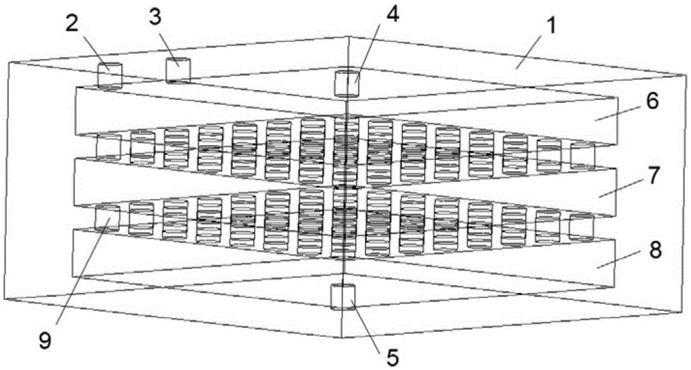
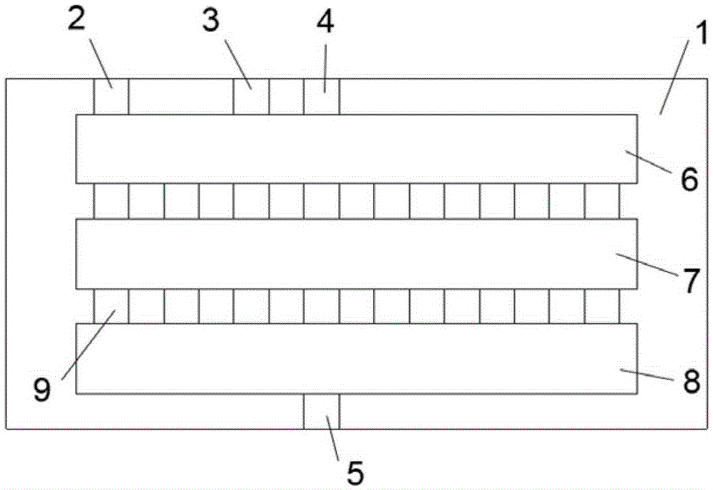
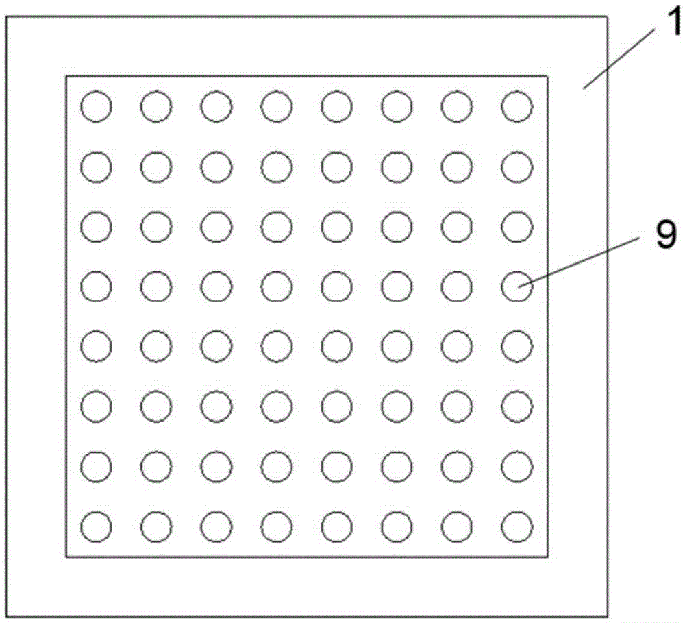
[0044] Design the supporting structure of the battery unit and make it by 3D printing. The material is ABS plastic, and the battery unit is a cube with a volume of 10cm 3 , wherein the volumes of the electrolyte chamber, the first liquid metal chamber (hereinafter referred to as liquid metal chamber 1) and the second liquid metal chamber (hereinafter referred to as liquid metal chamber 2) are all 2 cm 3 , the shapes are all cubes; the shapes of the injection hole, the exhaust hole, the sieve hole, the first electrode guide hole (hereinafter referred to as the electrode guide hole 1) and the second electrode guide hole (hereinafter referred to as the electrode guide hole 2) are all circular, The diameter of the injection hole and the exhaust hole is 0.5mm, the diameter of the electrode guide hole 1 and the electrode guide hole 2 is 0.2mm, and the diameter of the mesh is 1mm; the first liquid metal (hereinafter referred to as l...
Embodiment 2
[0045] The process of embodiment 2 is as follows:
[0046] Design the supporting structure of the battery unit and make it by 3D printing. The material is silica gel, and the battery unit is a cube with a volume of 100cm 3 , where the volume of the electrolyte chamber is 15 cm 3 , the shape is an ellipsoid, and the volumes of metal chambers 1 and 2 are both 20cm 3 , the shape is cube; the shape of injection hole, vent hole, sieve hole, electrode guide hole 1 and 2 is circular, the diameter of injection hole and vent hole is 2mm, and the diameter of electrode guide hole 1 and 2 is 0.2mm mm, the sieve diameter is 1mm; the liquid electrode metal 1 has a melting point of 138°C and a volume of 15cm 3 BiSn 42 , electrode metal 2 has a melting point of 15.6°C and a volume of 15 cm 3 GaIn 24.5 , the pH value of the electrolyte is 12.5, the volume is 22cm 3 of NaOH solution. In an incubator with a temperature of 180 °C, the liquid BiSn 42 , NaOH solution and liquid Ga 62.5 In ...
Embodiment 3
[0047] The process of embodiment 3 is as follows:
[0048] The supporting structure of the designed battery cell is made by microfluidic technology, the material is PDMS, the battery cell is a cube, and the volume is 1cm 3 . Among them, the volume of the electrolyte chamber is 0.2cm 3 , the shape is an ellipsoid, and the volumes of metal chambers 1 and 2 are both 0.25cm 3 , the shape is cube; the shape of injection hole, vent hole, sieve hole, electrode guide hole 1 and 2 is circular, the diameter of injection hole and vent hole is 0.3mm, and the diameter of electrode guide hole 1 and 2 is 0.2mm, the mesh diameter is 50μm; electrode metal 1 has a melting point of -38°C and a volume of 0.2cm 3 Hg, electrode metal 2 has a melting point of 15.6°C and a volume of 0.2cm 3 GaIn 24.5 , the electrolyte uses a pH value of 3 and a volume of 0.3cm 3 HCl solution. Liquid Hg, HCl solution and liquid GaIn were mixed with a syringe at room temperature 24.5 Inject into the metal chamb...
PUM
| Property | Measurement | Unit |
|---|---|---|
| melting point | aaaaa | aaaaa |
| diameter | aaaaa | aaaaa |
| diameter | aaaaa | aaaaa |
Abstract
Description
Claims
Application Information
 - R&D Engineer
- R&D Manager
- IP Professional
- Industry Leading Data Capabilities
- Powerful AI technology
- Patent DNA Extraction
Browse by: Latest US Patents, China's latest patents, Technical Efficacy Thesaurus, Application Domain, Technology Topic, Popular Technical Reports.
© 2024 PatSnap. All rights reserved.Legal|Privacy policy|Modern Slavery Act Transparency Statement|Sitemap|About US| Contact US: help@patsnap.com


