Total-manganese flow battery
A liquid flow battery and single cell technology, applied in the direction of regenerative fuel cells, fuel cell components, etc., can solve problems such as cross-contamination costs, achieve long cycle life, simple structure and manufacturing process, and solve cross-contamination effects
- Summary
- Abstract
- Description
- Claims
- Application Information
AI Technical Summary
Problems solved by technology
Method used
Image
Examples
Embodiment
[0020] Electrolyte configuration:
[0021] Electrolyte: Electrolyte 40ml, which contains 1.0moldm -3 MnSO 4 , 1 mold m -3 K 2 SO 4 , 0.1moldm -3 h 2 SO 4 .
[0022] Battery Assembly:
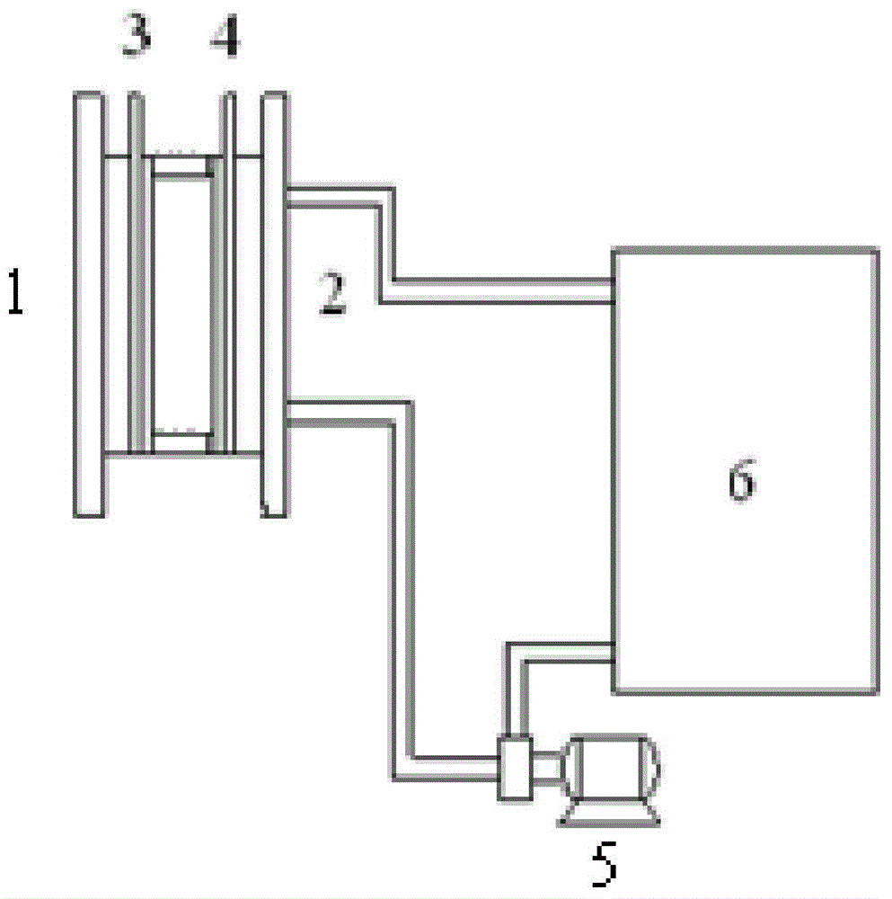
[0023] Positive terminal plate, positive electrode 3x3cm in order of single cell 2 Nickel plate, negative electrode 3x3cm 2 Nickel plate, negative terminal plate. Single battery structure and system see figure 1 .
[0024] Battery test:
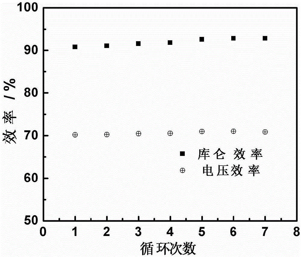
[0025] Electrolyte flow rate: 5ml / min; charge and discharge current density 15mA / cm 2 ; Charging for 1h, the discharge cut-off voltage is 0V. For battery performance see figure 2 , from the charge-discharge current density figure 2 It can be seen that at 15mA / cm 2 ; The charging time is 1h, and the average energy efficiency of the battery reaches about 75%.
PUM
 Abstract
Description
Claims
Application Information
 - R&D
- Intellectual Property
- Life Sciences
- Materials
- Tech Scout
- Unparalleled Data Quality
- Higher Quality Content
- 60% Fewer Hallucinations
Browse by: Latest US Patents, China's latest patents, Technical Efficacy Thesaurus, Application Domain, Technology Topic, Popular Technical Reports.
© 2025 PatSnap. All rights reserved.Legal|Privacy policy|Modern Slavery Act Transparency Statement|Sitemap|About US| Contact US: help@patsnap.com


