Eureka AIR delivers breakthrough ideas for toughest innovation challenges, trusted by R&D personnel around the world.

Multifunctional field partial discharge test system

A test system and field bureau technology, applied in the direction of testing dielectric strength, etc., can solve the problems of inability to carry out partial discharge test work normally, increase the workload of field test personnel, and affect the reliability of partial discharge test data, so as to avoid sudden Situation and test interruptions, improved work efficiency, and the effect of sensitive detection

Active Publication Date: 2016-01-27
EXAMING & EXPERIMENTAL CENT OF ULTRAHIGH VOLTAGE POWER TRANSMISSION COMPANY CHINA SOUTHEN POWER GRID
View PDF8 Cites 4 Cited by
  • Summary
  • Abstract
  • Description
  • Claims
  • Application Information

AI Technical Summary

Problems solved by technology

The existence of these interference signals makes the interference fed back to the on-site partial discharge instrument particularly obvious, and it is impossible to carry out partial discharge test work normally
Moreover, due to the limitations of the on-site partial discharge test system equipment, the uncertainty of the capacity and inductive reactance of the entire test circuit, and the selection of detection impedance, there are also problems. The corresponding test circuit cannot select the most suitable detection impedance, which will reduce the partial discharge. The sensitivity of the detection has an impact on the reliability of the subsequent partial discharge detection data, causing errors
The capacity of different electrical equipment is also different, and the tuning capacity of the detection impedance required for the partial discharge test is also different. Different types of detection impedance are easy to confuse, which increases the workload of the field test personnel.

Method used


Image

  • Multifunctional field partial discharge test system
  • Multifunctional field partial discharge test system
  • Multifunctional field partial discharge test system

Examples


Embodiment Construction

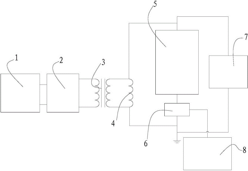
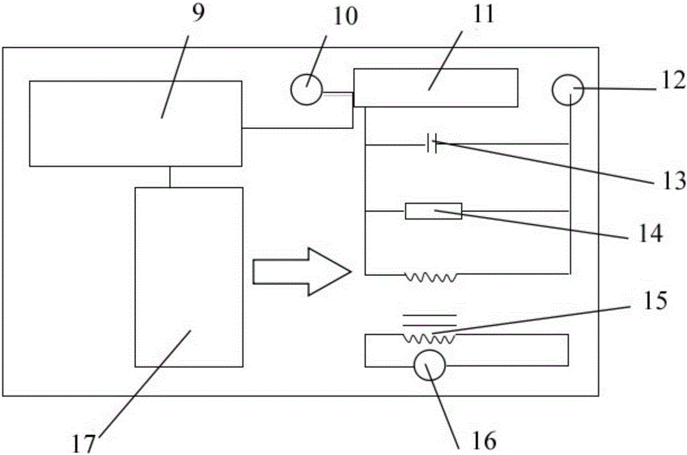
[0024] Such as Figure 1-2As shown, a multifunctional on-site partial discharge test system includes a voltage regulation controller 1, a variable frequency power supply 2, an excitation transformer 3, a reactor 4, a test object 5, a detection impedance 6, a pulse generator 7 and an electric pulse bureau. Amplifier 8, the input end of the voltage regulating controller 1 is connected to the power frequency voltage, the output end of the voltage regulating controller 1 is connected to the input end of the variable frequency power supply 2, the output end of the variable frequency power supply 2 is connected to the input end of the excitation transformer 3, and the excitation The output terminal of the transformer 3 is connected in parallel with the reactor 4, the reactor 4, the tested product 5, and the detection impedance 6 are connected in series to form a detection circuit, the end connected to the detection impedance 6 and the reactor 4 is grounded, and the pulse generator 7 ...


PUM


Abstract

The invention provides a multifunctional field partial discharge test system comprising a voltage regulation controller, a variable-frequency power supply, an excitation transformer, an electric reactor, a tested product, detection impedance, a pulse generator and an electric pulse partial discharge detector. The detection impedance comprises a low-noise amplification circuit, an adjustable capacitor module, an adjustable resistor module, an adjustable inductor module, a signal input end, a signal output end, a grounding end and a power supply module. The adjustable capacitor module, the adjustable resistor module and the adjustable inductor module are connected in parallel to form an RLC module. One end of the low-noise amplification circuit is connected with the signal input end and the power supply module. The other end of the low-noise amplification circuit is connected with one end of the RLC module. The other end of the RLC module is connected with the grounding end. The signal output end is connected in parallel with the RLC module.

Description

technical field [0001] The invention mainly relates to an on-site partial discharge test system for a rheology converter, and mainly relates to a multifunctional on-site partial discharge test system. Background technique [0002] Partial discharge refers to a kind of electrical discharge in which the insulation system of power equipment is partially broken down. It is due to the presence of weak electricity inside the insulation of the equipment or defects caused during the production process, and repeated breakdown and extinguishment occur under the action of high voltage strength. Partial discharge will produce charge exchange and generate high-frequency current pulses. Through the corresponding detection circuit, the detection impedance is used to convert the signal to the electric pulse partial discharge instrument for analysis and processing, so as to achieve the function of detecting partial discharge. [0003] In the field partial discharge test system, the detectio...

Claims


Application Information

Patent Timeline
Patent Type & Authority Applications(China)
IPC IPC(8): G01R31/12
Inventor 宋作森周海滨曹超夏谷林楚金伟刘东王竣张长虹陈伟民骆晓龙高嘉楼狄陆春玉
Owner EXAMING & EXPERIMENTAL CENT OF ULTRAHIGH VOLTAGE POWER TRANSMISSION COMPANY CHINA SOUTHEN POWER GRID
Why Eureka
Eureka Blog
Learn More