
Belt loop sewing method and belt loop sewing sewing machine

A technology of sewing machine and belt ring, which is applied in the direction of sewing machine components, sewing equipment, cloth pressing mechanism, etc., can solve the problems of increased sewing thread consumption, reduced operating efficiency, and damaged commodity value, and achieves reduction in consumption and number of stitches The effect of reduction and concentration relaxation of stitches

Active Publication Date: 2019-09-06
JUKI CORP
View PDF7 Cites 0 Cited by
  • Summary
  • Abstract
  • Description
  • Claims
  • Application Information

AI Technical Summary

Problems solved by technology

[0022] Therefore, an increase in thread consumption during sewing of the belt loop B and a decrease in working efficiency due to an increase in sewing time occur.
[0023] In addition, since the belt loop B is dragged when turning back at the seam line L2, it becomes a cause of lifting or misalignment of the sewn part of the fabric C.
[0024] In addition, there is a problem that the stitches L1 to L3 are concentrated in the narrow portion on the back side of the cloth C, thereby degrading the appearance and deteriorating the commercial value.

Method used


Image

  • Belt loop sewing method and belt loop sewing sewing machine
  • Belt loop sewing method and belt loop sewing sewing machine
  • Belt loop sewing method and belt loop sewing sewing machine

Examples


Embodiment Construction

[0128] [Outline of sewing device]

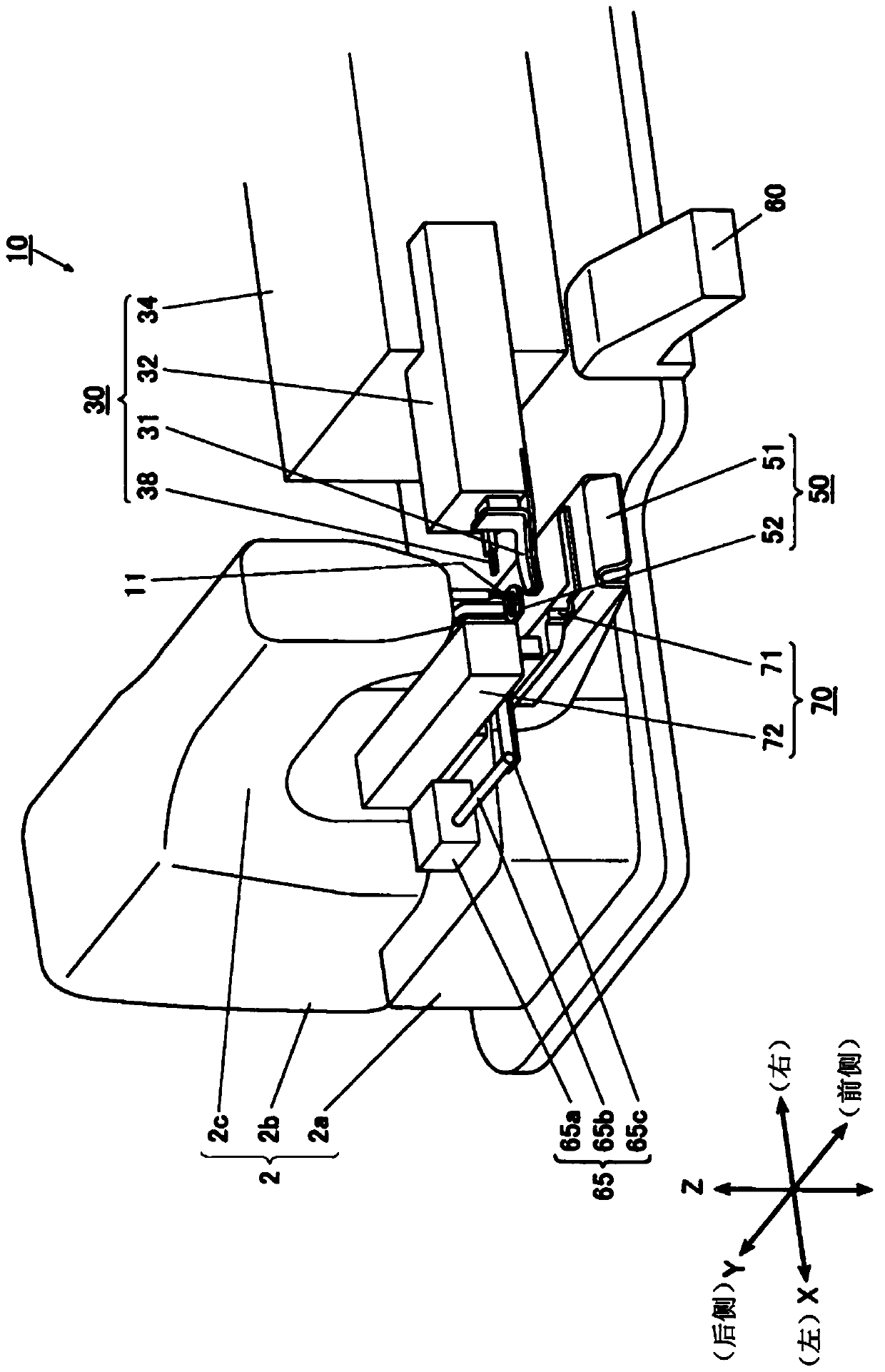
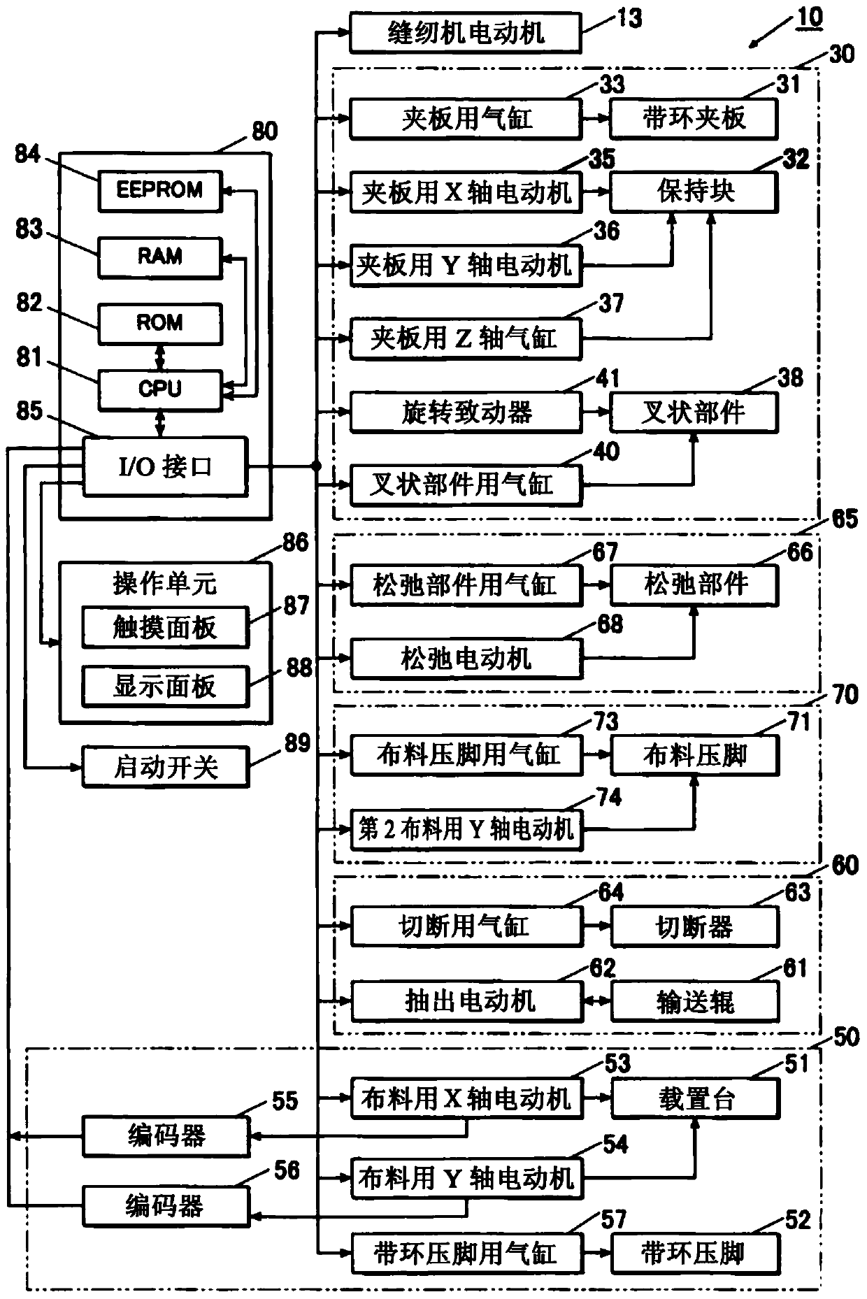
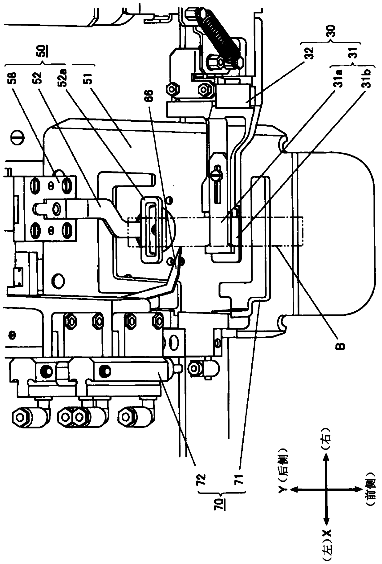
[0129] Hereinafter, embodiments of the present invention will be described in detail based on the drawings. figure 1 It is a perspective view showing the whole of the belt loop sewing machine 10 according to this embodiment, figure 2 is the block diagram representing the control system, image 3 It is an oblique view around the needle.

[0130] The belt loop sewing machine 10 has: an unillustrated sewing needle vertical movement mechanism, which moves the sewing needle 11 up and down; a clamp mechanism 30, which has a belt loop clamp 31 for clamping the belt loop B facing a predetermined direction; A loop supply mechanism 60 that supplies the belt loop B to the clamp mechanism 30 ; , the belt loop presser 52 presses the belt loop B by descending to the mounting table 51; the loosening mechanism 65 has a loosening member 66 for loosening the belt loop of the belt loop B; the cloth presser foot mechanism 70 has The cloth presser 71 hold...


PUM


Abstract

The invention provides a band ring sewing machine, and the machine achieves the Z-shaped sewing of one end part of band ring and reduces the stitch number. The machine is provided with a sewing needle up / down movement mechanism; a band ring clamping board; a band ring pressing pin; a carrying table; a cloth pressing pin; a first moving mechanism which enables the band ring pressing pin and the carrying table to move; a second moving mechanism which enables cloth to move; a clamping board moving mechanism which enables the band ring clamping board to move; a control device; an insertion part; and an insertion part movement mechanism. The control device carries out the following control: folding stitch forming control: forming a folding stitch at one end part of the band ring clamped by the band ring clamping board; insertion part configuration control: configuring an insertion part in a gap between the cloth and the band ring between the folding stitch and a clamping position referred by the band ring clamping board; folding control: enabling the insertion part to move towards the folding stitch, and forming a state of band ring folding through the insertion part; folding sewing control: forming a stitch which enables the band ring to be sewed towards the stitch, so as to maintain the folding state of the band ring.

Description

technical field [0001] The present invention relates to a loop sewing method and a loop sewing sewing machine. Background technique [0002] The belt loop sewing machine is used to sew a belt loop through which a belt is passed to fabric such as trousers. The belt loop is a long and thin strip of cloth, and there are various sewing methods for sewing it to the cloth. As one of them, there is known a sewing method in which, as shown in FIG. 20(A), one end of the belt loop is folded back twice to form a Z-shape for sewing. [0003] A conventional belt loop sewing machine has: a belt loop clamp 31 for gripping the belt loop in a predetermined direction (set as the Y direction); a mounting table 51 for placing the material; 71, which presses and holds the cloth from above; the belt loop presser foot 52, which presses the belt loop B from above with the smaller frame through which the sewing needle passes; the slack part 66, which makes the belt loop B have slack; Motor, it ca...

Claims


Application Information

Patent Timeline
Patent Type & Authority Patents(China)
IPC IPC(8): D05B23/00D05B29/02
Inventor 安田俊介山谷惠子
Owner JUKI CORP
Learn More