Screw elements and method for manufacturing screw elements

A worm gear and component technology, applied in the field of double-shaft extruders, can solve the problems of difficulty, laborious manufacturing process, and cost-intensive, and achieve the effects of reducing structural delay, improving service life, and optimizing cooling.

Inactive Publication Date: 2016-01-27
CARL AUG PICARD
View PDF6 Cites 5 Cited by
  • Summary
  • Abstract
  • Description
  • Claims
  • Application Information

AI Technical Summary

Problems solved by technology

[0006] A disadvantage of known worm gear elements is that their manufacturing process is labor-intensive and cost-intensive
In addition, limited by traditional cutting methods and forming manufacturing methods, it is difficult or impossible to manufacture small diameters and specific internal and external geometries of worm gear elements when applying specific cemented carbides
[0007] Furthermore, through the use of hard metal and in combination with the hitherto applied manufacturing methods, the production of cooling channels in the worm gear element is very labor-intensive and can only be produced axially parallel, so that the outer contour cannot be cooled uniformly

Method used


Image

  • Screw elements and method for manufacturing screw elements
  • Screw elements and method for manufacturing screw elements
  • Screw elements and method for manufacturing screw elements

Examples


Embodiment Construction

[0025] For the following description, it should be emphasized that the present invention is not limited to these embodiments, nor is it limited to all or a plurality of features of the described feature combinations, but a single partial feature of each embodiment can be combined with other Partial features described above and below can also be combined with any features of other embodiments to form an essential part of the present invention.

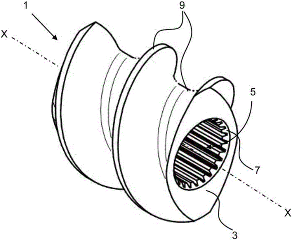
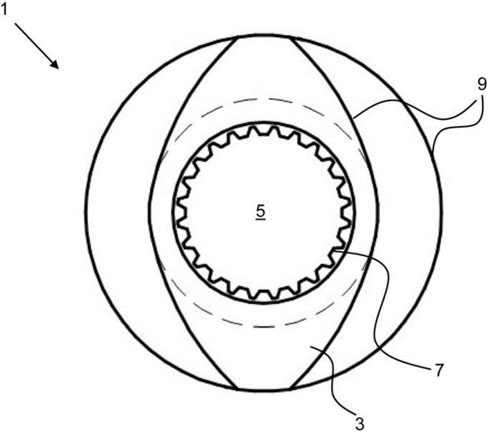
[0026] Figure 1a and 1b An embodiment of a worm gear element 1 according to the invention is shown. The worm gear element 1 is designed in particular for a co-rotating, closely intermeshing twin-shaft extruder, not shown. The worm gear element 1 comprises a worm gear body 3 with an axially extending through-hole 5 , internal teeth 7 for insertion on a bearing shaft and an outer contour 9 for providing an extrusion function. For use with such a twin-shaft extruder, said worm gear element 1 is pushed together with other worm gear eleme...


PUM

PropertyMeasurementUnit
thicknessaaaaaaaaaa
hardnessaaaaaaaaaa
hardnessaaaaaaaaaa

Abstract

A production method for screw elements (1) with a screw body (3) with an axially through-opening (5) with internal gearing (7) for mounting on a support shaft and an outer contour (9) for closely meshing twin-shaft extruders. A metallic powder material (13) is arranged step by step in layers in the direction of a production axis (Z-Z) on a work platform (11), wherein a laser beam (19) for each layer of the screw element (1) irradiates the powder material (13) according to the data of a three-dimensional model in a specific irradiation sequence at specific sites of the layer. The powder material (13) is melted, fully in places, and bonded with the directly underlying layer, so that after hardening of the layers, a complete, stable screw body (3) is produced. Further, the invention relates to a screw element produced in this way.

Description

technical field [0001] The present invention relates to a method especially for worm gear elements of co-rotating, closely meshing twin-shaft extruders. Furthermore, the invention relates to a worm gear element, in particular for closely intermeshing twin-shaft extruders rotating in the same direction, said worm gear element comprising a worm gear body with an axially extending through-bore for The internal teeth inserted on the support shaft and the external profile to provide the extrusion function. Background technique [0002] Worm gear elements of this type are used, for example, as part of twin-screw extruders in various fields of industry in which the processing of plastics is difficult. Worm gears used in twin-shaft extruders are constructed modularly and consist of a support shaft and a single worm gear element. The geometry of the worm gear elements is designed according to the task and function of the method technology of the twin-shaft extruder and is mounted a...

Claims


Application Information

Patent Timeline
Patent Type & Authority Applications(China)
IPC IPC(8): B22F3/115C23C24/10F16H55/22B29C48/03
CPCB29B7/489B29C48/03B29C48/2564B29C48/507B29C48/402B29C48/509Y02P10/25B22F10/47B22F10/38B22F10/25B33Y10/00B33Y80/00B23K9/044B22F5/085B01F27/1143
Inventor 米夏埃尔·布森贝克尔
Owner CARL AUG PICARD
Why Eureka
Try Eureka