Servo pump control hydraulic system

A hydraulic system and servo pump technology, applied in servo motors, servo motor components, fluid pressure actuating devices, etc., can solve the problems of low efficiency of hydraulic systems, large throttling losses, and difficulty in further improving efficiency.

Inactive Publication Date: 2016-01-13
山东富力世新型材料有限公司
View PDF4 Cites 10 Cited by
  • Summary
  • Abstract
  • Description
  • Claims
  • Application Information

AI Technical Summary

Problems solved by technology

[0002] Bending machines, hydraulic presses and other forging equipment are widely used in industrial enterprises. Due to the low efficiency of traditional hydraulic systems, the energy consumption of such equipment is generally high at present.
In order to save energy and improve efficiency, the energy saving of the hydraulic system of the bending machine is mainly based on the traditional electro-hydraulic synchronous bending machine. The three-phase asynchronous motor is changed to a servo motor, and the servo motor is controlled to drive the oil pump according to the required speed and torque. The valve controls the synchronization of the two oil cylinders. Due to the use of proportional valve control in this way, there is still a large throttling loss, the efficiency is difficult to further improve, and the cost is high. This is the deficiency of the existing technology.

Method used


Image

  • Servo pump control hydraulic system

Examples


Embodiment Construction

[0017] In order to clearly illustrate the technical features of the present solution, the present solution will be described below through specific embodiments and in conjunction with the accompanying drawings.

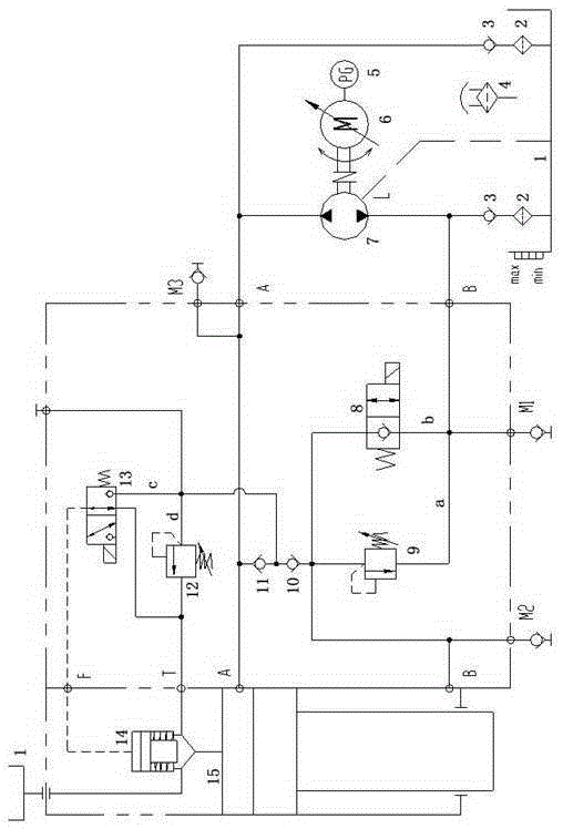
[0018] A servo pump-controlled hydraulic system includes an oil cylinder 15 and a bidirectional hydraulic pump 7 driven by a servo motor 6. The output shaft of the servo motor 6 is connected with the drive shaft of the hydraulic pump 7, and the servo motor 6 drives the hydraulic pump 7 clockwise or counterclockwise. Clock operation and stop of hydraulic pump 7 . The servo motor 6 has a built-in encoder 5, which is used to measure the angular displacement and rotational speed of the servo motor 6, and feed back the corresponding signal to the servo motor driver to form a closed-loop control loop, which improves the efficiency of the servo motor 6 to drive the hydraulic pump 7. control precision. Relying on the displacement sensor measuring the position of the piston r...


PUM


Abstract

The invention provides a servo pump control hydraulic system which comprises an oil cylinder and a two-way hydraulic pump driven by a servo motor. The hydraulic pump is connected with an oil tank. One end of an oil in / out opening of the hydraulic pump is connected with an upper cavity of the oil cylinder, and the other end of the oil in / out opening of the hydraulic pump is connected with a lower cavity of the oil cylinder through a branch a and a branch b. A back pressure valve is arranged on the branch a, and a poppet valve is arranged on the branch b. The branches between the oil in / out opening of the hydraulic pump and the oil tank are each provided with an oil supplementing one-way valve; the upper cavity of the oil cylinder is connected with a one-way valve II, and the lower cavity of the oil cylinder is connected with a one-way valve I; the one-way valve I is connected with a prefill valve through a branch c and a branch d, the one-way valve II is connected with the prefill valve through the branch c and the branch d, and the branch c is provided with an electromagnetic ball valve. Hydraulic oil flowing through the electromagnetic ball valve controls opening and closing of the refill valve, and the branch d is provided with a safety valve. By means of the hydraulic system, energy consumption can be greatly lowered, the operation efficiency of a hydraulic machine and the operation efficiency of a bending machine are improved, and oil consumption of the hydraulic system is reduced.

Description

technical field [0001] The invention relates to a servo pump-controlled hydraulic system, which belongs to the technical field of hydraulic control. Background technique [0002] Forging equipment such as bending machines and hydraulic presses are widely used equipment in industrial enterprises. Due to the low efficiency of traditional hydraulic systems, the energy consumption of such equipment is generally high at present. In order to save energy and improve efficiency, the energy saving of the hydraulic system of the press brake is mainly based on the traditional electro-hydraulic synchronous press brake, the three-phase asynchronous motor is changed to a servo motor, and the servo motor is controlled to drive the oil pump according to the required speed and torque. The valve controls the synchronization of the two oil cylinders. Due to the proportional valve control, this method still has a large throttling loss, it is difficult to further improve the efficiency, and the ...

Claims


Application Information

Patent Timeline
Patent Type & Authority Applications(China)
IPC IPC(8): F15B11/08F15B13/04
Inventor 刘海龙潘伟杨牧樊泽贵
Owner 山东富力世新型材料有限公司
Why Eureka
Try Eureka