Movable cantilever frame device for civil engineering construction

A kind of industrial and civil engineering, mobile technology, applied in the direction of construction, building structure, scaffolding accessories, etc., can solve the problems of poor overall use effect, automatic downward movement of the bearing plate, broken and slipped bolts, etc., to achieve convenient stability and safety. Use, prevent self-dropping, and balance the effect of force

Pending Publication Date: 2022-07-12
樊宝云
View PDF1 Cites 0 Cited by
  • Summary
  • Abstract
  • Description
  • Claims
  • Application Information

AI Technical Summary

Problems solved by technology

[0004] However, there are still the following problems in the process of using the movable lifting frame device for industrial and civil construction projects in the prior art: the lifting adjustment of the load plate is manually adjusted, which is time-consuming and laborious, and the operation is particularly inconvenient. At the same time, After the load plate is lifted and adjusted, the load plate is limited and fixed by tightening the locking bolt with a wrench and squeezing the movable rod. During use, the bolts are easy to break and slip off, causing the load plate to automatically move down under force, which has a relatively large Big safety hazard, the overall use effect is not good

Method used


Image

  • Movable cantilever frame device for civil engineering construction
  • Movable cantilever frame device for civil engineering construction
  • Movable cantilever frame device for civil engineering construction

Examples


Embodiment

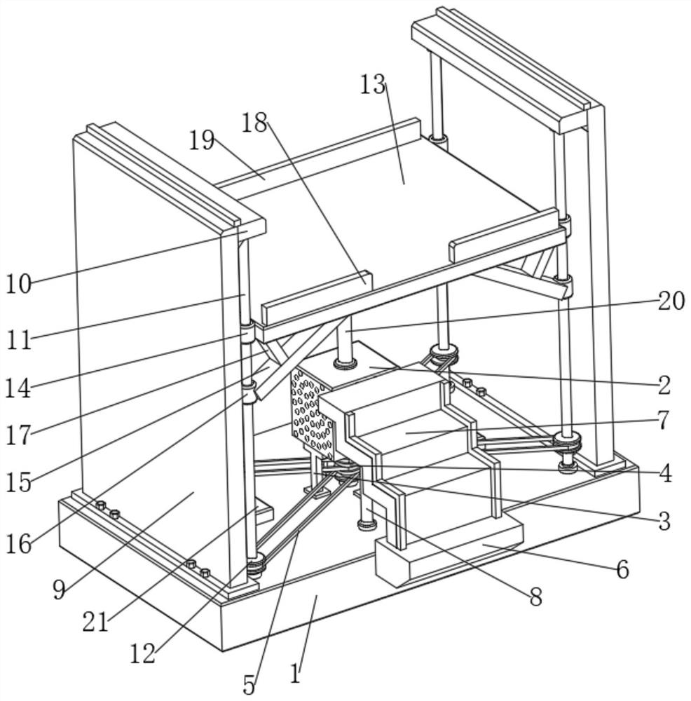
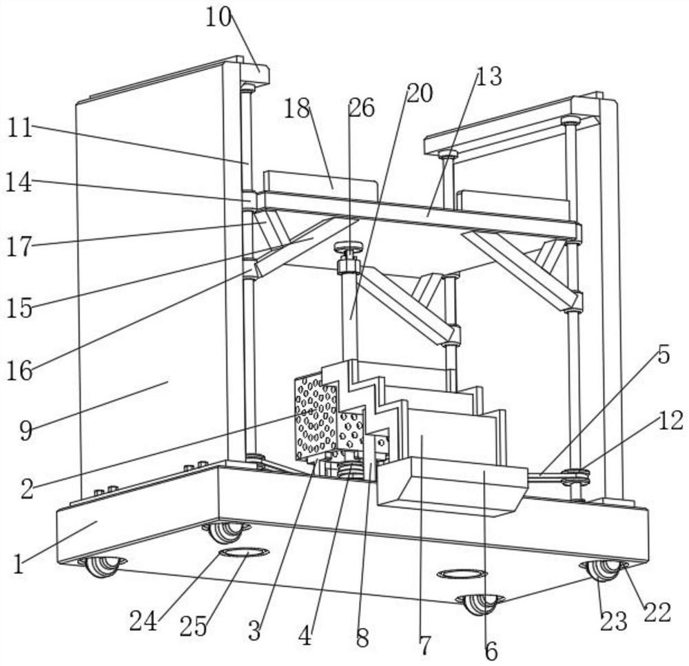
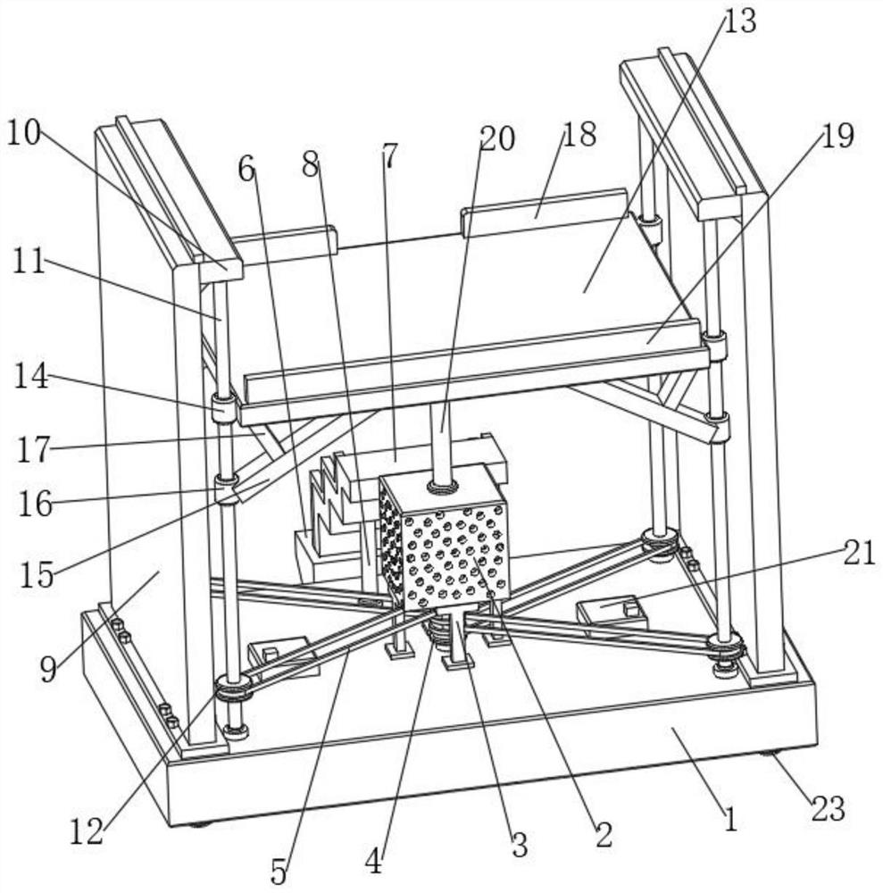
[0032] see figure 1 , figure 2 , image 3 , Figure 4 , Figure 5 and Image 6, the present invention provides the following technical solutions: a movable pick-up device for industrial and civil construction projects, comprising a base plate 1, a chassis 2 is arranged in the middle position of the upper end of the base plate 1, and a number of support rods are arranged around the bottom of the chassis 2. 3. The upper and lower ends of the support rod 1 3 are respectively fixedly connected with the bottom end of the chassis 2 and the upper end of the bottom plate 1, and the support rod 1 3 is a "T"-shaped structure. The inner upper end of the chassis 2 is fixed with a positive and negative motor 27, the output end of the positive and negative motor 27 is provided with a transmission shaft, and the bottom end of the transmission shaft is fixed with a main pulley 4, and the bottom end of the main pulley 4 and the upper end of the bottom plate 1 pass through The rotating sh...


PUM


Abstract

The invention belongs to the technical field of engineering construction, and particularly relates to a movable cantilever device for civil engineering construction, which comprises a bottom plate, a case is arranged in the middle of the upper end of the bottom plate, a plurality of support rods I are arranged on the periphery of the bottom of the case, and a positive and negative motor is fixed at the inner upper end of the case. A transmission shaft is arranged at the output end of the forward and reverse motor, a main belt wheel is fixed to the bottom end of the transmission shaft, a plurality of belts are connected to the main belt wheel in a sleeving mode, side plates are fixed to the two sides of the upper end of the bottom plate, an ejector rod is fixed to one side of the upper end of each side plate, and screw rods are arranged on the two sides of the bottom end of each ejector rod; the upper end and the lower end of the screw rod are rotationally connected with the top rod and the bottom plate through rotating shafts correspondingly, auxiliary belt wheels are fixed to the periphery of the outer portion of the bottom end of the screw rod, and the auxiliary belt wheels are in transmission connection with the main belt wheels through belts, bearing and descending are easy and convenient, supporting is stable and firm, using is safe and convenient, the overall using effect is good, and construction and using are convenient.

Description

technical field [0001] The invention belongs to the technical field of engineering construction, and in particular relates to a movable bracket device for the construction of industrial and civil construction projects. Background technique [0002] Building construction is a production activity that people use various building materials, machinery and equipment to build various building products in a certain space and time according to a specific design blueprint. In the construction of high-rise buildings, it is often necessary to use The scaffolding device is divided into one pick per layer and multi-layer cantilever. The traditional steel scaffolding can not meet the requirements of the project construction period. It takes a lot of time to build, dismantle, and modify, and the stacking of steel pipes and other materials takes up a lot of time. Sometimes, due to the large size of the shelves and the staggered packing, it will take a long time to dismantle, which greatly a...

Claims


Application Information

Patent Timeline
Patent Type & Authority Applications(China)
IPC IPC(8): E04G1/18E04G1/15E04G1/24E04G5/00E04G5/02E04G5/10E04G5/14
CPCE04G1/18E04G1/15E04G1/24E04G5/00E04G5/02E04G5/10E04G5/14E04G2001/242
Inventor 樊宝云陈学德秦学庆
Owner 樊宝云
Why Eureka
Try Eureka