
Vapor mixing device reducing NOx emission

A technology of mixing device and mist, which is applied in the transportation of non-flammable liquid/gas, combustion method, combustion equipment, etc., can solve the problems of difficulty in reducing NOx emission, high maintenance cost, and difficulty in meeting requirements, and achieves reduction of reaction probability, Simple structure and obvious effect

Inactive Publication Date: 2016-01-06
SHANGHAI WISEBOND TECH
View PDF6 Cites 3 Cited by
  • Summary
  • Abstract
  • Description
  • Claims
  • Application Information

AI Technical Summary

Problems solved by technology

[0003] Industrial oil and gas burner emission reduction technologies are mainly divided into pre-treatment and post-treatment: pre-treatment generally refers to the use of superb low NOx combustion technology to suppress or reduce NOx emissions, such as staged combustion technology, flue gas recirculation technology, thick-lean combustion technology, etc. ; while post-treatment refers to the denitrification of flue gas after combustion. This technology has a large investment cost and high follow-up maintenance costs
For the high requirements in Beijing and other regions - from April 2017, the NOx emission of newly installed gas-fired industrial boilers shall not exceed 30 mg. The current pre-treatment methods have been difficult to meet the requirements, especially the flames in some small combustion chambers are more difficult to reduce. NOx emissions

Method used


Image

  • Vapor mixing device reducing NOx emission
  • Vapor mixing device reducing NOx emission
  • Vapor mixing device reducing NOx emission

Examples


Embodiment Construction

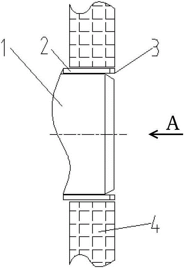
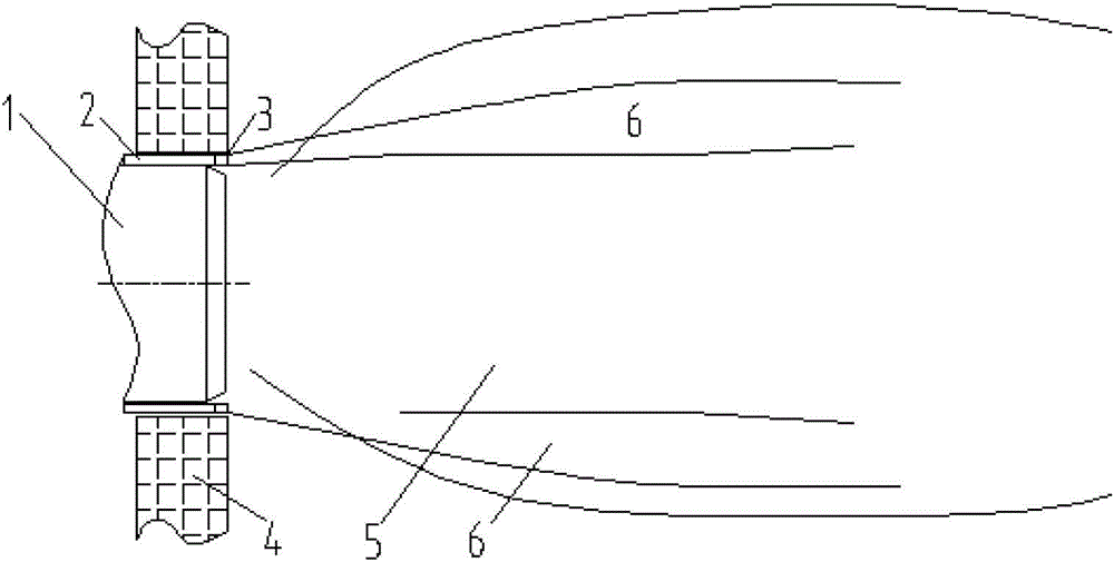
[0015] figure 1 It is a schematic diagram of the structure of the present invention, figure 2 for figure 1 A schematic diagram of the structure. It can be seen from the figure that the mist-steam mixing device for reducing NOx emissions includes a burner throat and a furnace combustion chamber. The spray gun 2 is arranged in the same direction and parallel to the axis of the burner throat 1, and the end of the spray gun 2 facing the furnace combustion chamber is equipped with a spray gun head 3. The tail end of the spray gun 2 is connected to the high-pressure water / steam pipeline .

[0016] The number of the spray guns 2 is 3-20, which are evenly distributed along the outer periphery of the burner throat 1 .

[0017] When the pipeline connected to the tail end of the spray gun 2 is high-pressure water, the corresponding spray gun head 3 is a mechanical atomizing head.

[0018] When the pipes connected at the ends of the spray guns 2 contain steam, the corresponding spra...


PUM


Abstract

The invention provides a vapor mixing device reducing NOx emission, aims at achieving the technical purpose of mixing atomized vapor with flames and reducing NOx emission of industrial fuel oil and fuel gas combustors and belongs to the technical field of emission reduction of the industrial fuel oil and fuel gas combustors. The vapor mixing device reducing NOx emission is characterized in that a plurality of spray guns are evenly arranged on the periphery of the outer side of a throat opening of a combustor; the spray guns and the axis of the throat opening of the combustor are arranged in the same direction in parallel; the ends, facing a hearth combustion chamber, of the spraying guns are provided with spray gun heads; and the tail ends of the spray guns are communicated with a high-pressure water / vapor pipeline. When the tail ends of the spray guns are connected with high-pressure water, the corresponding spray gun heads are mechanical atomization heads. When vapor exists in the pipeline, axial spraying through holes are formed in the middles of the corresponding spray gun heads. The mixing device is simple in structure, a combustor body does not need to be modified, running is stable, and the effect is obvious. As shown by a plurality of field test results, when gas is combusted, the NOx emission concentration can be reduced by 25%, and when oil is combusted, the NOx emission concentration can be reduced by 10-30%.

Description

technical field [0001] The invention relates to a mist-steam mixing device for reducing NOx emissions from industrial fuel gas burners, which mixes atomized water vapor with flames to achieve the purpose of reducing NOx emissions from industrial fuel gas burners, and belongs to the technical field of industrial fuel / gas burner emission reduction . Background technique [0002] At present, NOx emission from industrial oil and gas burners is one of the main causes of air pollution and smog. Out of our common earth and environmental protection considerations, in order to reduce NOx emissions from industrial oil and gas burners, the NOx emission standards of countries all over the world have been greatly improved. [0003] Industrial oil and gas burner emission reduction technologies are mainly divided into pre-treatment and post-treatment: pre-treatment generally refers to the use of superb low NOx combustion technology to suppress or reduce NOx emissions, such as staged combu...

Claims


Application Information

Patent Timeline
Patent Type & Authority Applications(China)
IPC IPC(8): F23L7/00
Inventor 陈宝明杨苏莉
Owner SHANGHAI WISEBOND TECH
Learn More