Composite seepage preventing structure for large karst cave in karst region and construction method thereof
A large-scale karst cave and composite anti-seepage technology, which is applied in the direction of basic structure engineering, buildings, sheet pile walls, etc., can solve the problems of difficult construction period guarantee, large manpower and financial resources, and large engineering volume, and achieve low construction strength, less input materials, The effect of improving construction efficiency
- Summary
- Abstract
- Description
- Claims
- Application Information
AI Technical Summary
Problems solved by technology
Method used
Image
Examples
Embodiment 1
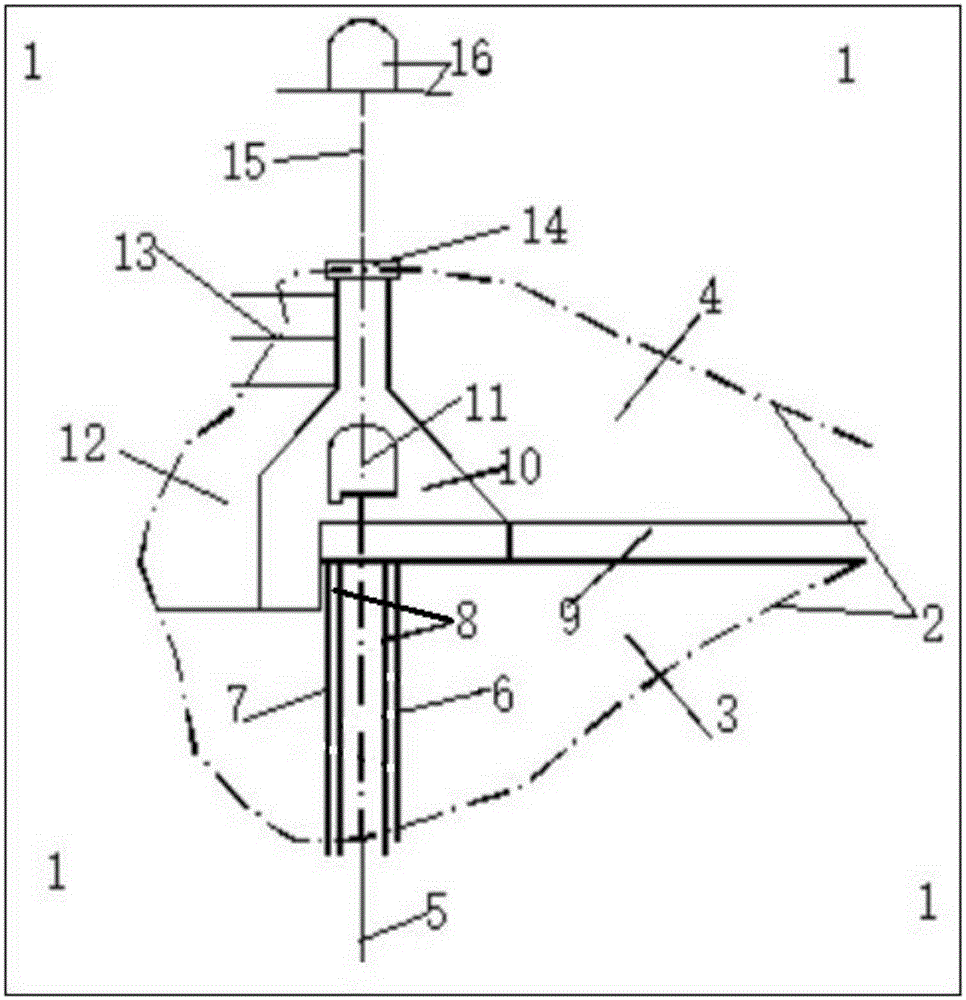
[0050] There is a karst cave 2. The karst cave 2 develops along the middle of the anti-seepage line. It is 47m long and 51m wide along the anti-seepage axis. The thickness of the karst cave filling is 29m-41m. 3 , which is a giant karst cave with filled halls. The fillings are mainly clay and silty clay, and there are partially dissolved broken stones. The original treatment plan was to backfill concrete after excavating all the fillings. However, due to the difficulty in the layout of the construction branch holes after the disclosure, the estimated construction period is as long as 30 months, the processing cost budget is as high as 71 million yuan, and there are many hidden dangers in construction safety. state. After long-term theoretical research and repeated site surveys, a more effective construction method has been summed up for the above-mentioned karst caves and similar karst caves. The construction steps are as follows:
[0051] ①Clean the surface of the cave 2, le...
Embodiment 2
[0063] In the steps described in Embodiment 1, the step ② can also adopt the following arrangement:
[0064] On the anti-seepage axis and on the downstream karst cave filling area 3, two rows of filling swirl holes 7 are arranged symmetrically, with a row distance of 1.0m, and steel pipes are installed between two adjacent filling swirl holes 7 in each row Pile 6, so that the distance between each filling spray hole 7 and the adjacent steel pipe pile 6 is 0.8m, and at least two rows of long-orifice pipes 8 are installed in the steel pipe pile 6, and the long-orifice pipe 8 and the steel pipe pile 6 The lower ends of the pipe piles 6 are all 3-5m deep into the bedrock; the high-pressure pouring process is used to pour concrete into the steel pipe pile 6 and the long-orifice pipe 8 under high pressure, and at the same time, the high-pressure rotary spraying process is used to pour concrete into the rotary spray hole 7 of the filling. The high-pressure rotary spraying makes it fl...
PUM
 Abstract
Description
Claims
Application Information
 - R&D
- Intellectual Property
- Life Sciences
- Materials
- Tech Scout
- Unparalleled Data Quality
- Higher Quality Content
- 60% Fewer Hallucinations
Browse by: Latest US Patents, China's latest patents, Technical Efficacy Thesaurus, Application Domain, Technology Topic, Popular Technical Reports.
© 2025 PatSnap. All rights reserved.Legal|Privacy policy|Modern Slavery Act Transparency Statement|Sitemap|About US| Contact US: help@patsnap.com

