A water-driven double-rotating splash device

A technology of water flow driving and splashing device, applied in water shower cooler, direct contact heat exchanger, heat exchanger type, etc., can solve uneven distribution, prone to umbrella-shaped water film and hollow phenomenon, and the effect is not very good and so on

Active Publication Date: 2017-01-25
HOHAI UNIV CHANGZHOU
View PDF5 Cites 0 Cited by
  • Summary
  • Abstract
  • Description
  • Claims
  • Application Information

AI Technical Summary

Problems solved by technology

[0003] However, the splashing devices currently used in China cannot fully meet the above requirements, and there are various deficiencies, such as the water droplets formed by the gravity splashing type splashing device are larger, the splashing range is small and the distribution is uneven; the water flow of the rotary spraying type splashing device It rotates and flows out inside the shell, but it needs to consume part of the water head; the reflective splash device is divided into two types, the fixed splash plate is prone to umbrella-shaped water film and hollow phenomenon; the splash plate is divided into fixed and movable parts, The blades of the moving part driven by the impact of the water flow rotate, the water droplets are small, and the splash range is wide, but relying on the superposition of the splash range of adjacent splash devices and the coverage of water seedlings to solve the hollow problem, the effect is not very good
Moreover, most of the splashing devices are equipped with a support frame, and the support frame is within the spray range, which hinders the spreading of water droplets, resulting in less water near the support frame and uneven distribution.

Method used


Image

  • A water-driven double-rotating splash device
  • A water-driven double-rotating splash device
  • A water-driven double-rotating splash device

Examples


Embodiment Construction

[0023] In order to enable those skilled in the art to better understand the technical solutions in the present application, the technical solutions in the embodiments of the present application will be clearly and completely described below in conjunction with the drawings in the embodiments of the present application. Obviously, the described The embodiments are only some of the embodiments of the present application, but not all of them. Based on the embodiments in this application, all other embodiments obtained by persons of ordinary skill in the art without creative efforts shall fall within the scope of protection of this application.

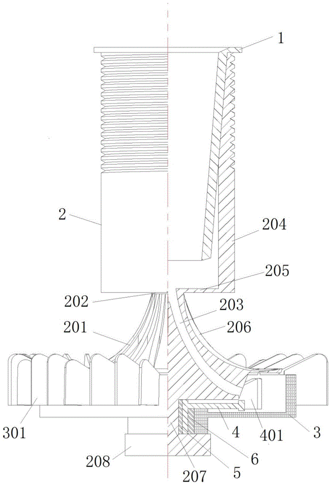
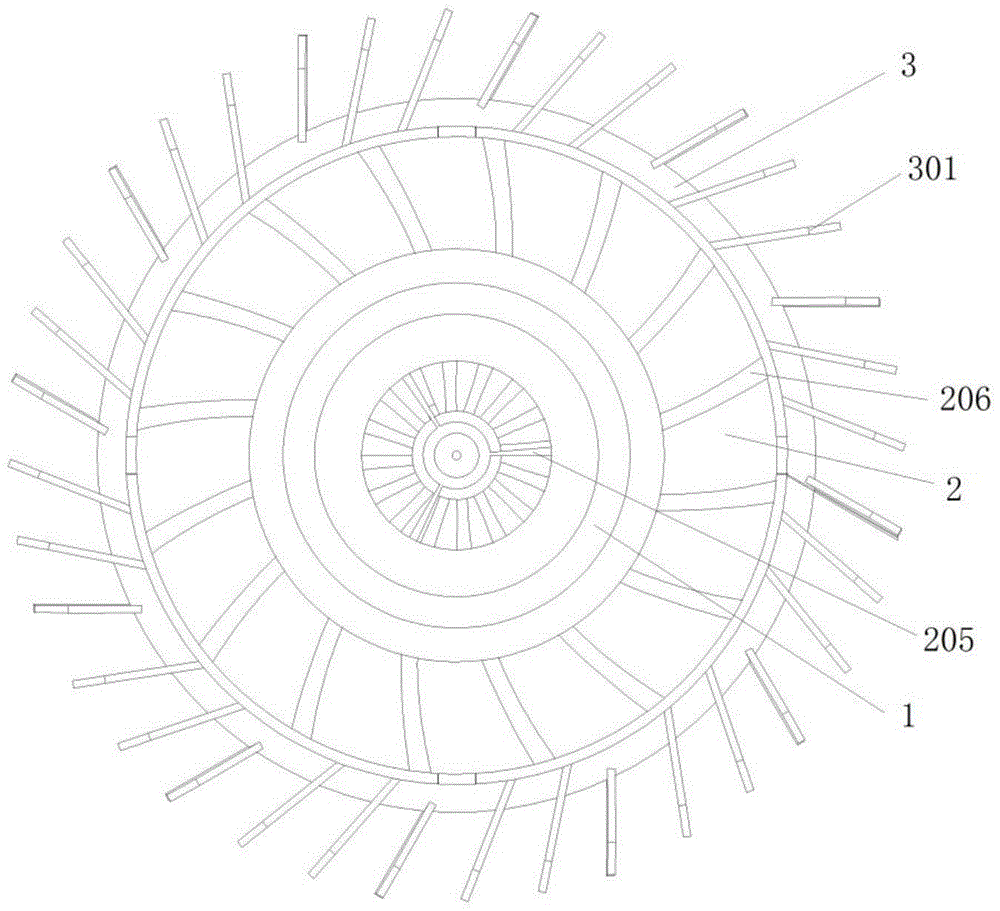
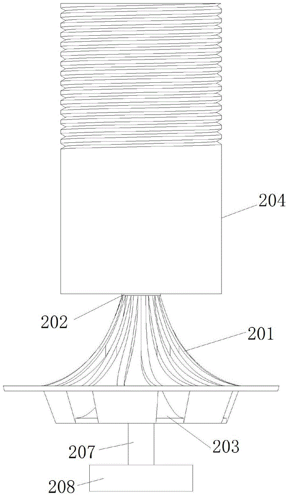
[0024] as attached Figure 1-5 As shown, a water-flow-driven double-rotating splashing device includes a guide tube 1, a splashing water distribution plate 2, a large runner 3, a small runner 4, a first rolling bearing 5 and a second rolling bearing 6, and the splashing water Diverter plate 2 is an integral structure, including conical p...


PUM


Abstract

The invention discloses a dual-rotation type splashing device driven through water flow. The dual-rotation type splashing device driven through the water flow comprises a guide pipe, a splashed water distributing tray, a big turning wheel, a small turning wheel, a first rolling bearing and a second rolling bearing. The guide pipe is installed in a cylindrical connector of the splashed water distributing tray. The small turning wheel is arranged below the splashed water distributing tray through a connection shaft rod and the first rolling bearing. The big turning wheel is arranged below the small turning wheel through the connection shaft rod and the second rolling bearing. According to the dual-rotation type splashing device driven through the water flow, the water flow is accelerated by using the structure of the splashing device fully, hollow phenomena are reduced, water drops can splash out more evenly due to the fact that obstruction of a traditional supporting frame is avoided, and the water distribution performance of the splashing device can be improved.

Description

technical field [0001] The invention relates to the technical field of cooling equipment, in particular to a water-flow-driven double-rotating splash device. Background technique [0002] As a kind of cooling equipment, cooling tower is widely used in thermal power generation, petrochemical industry, air conditioning and refrigeration and other fields. The cooling water carrying waste heat is distributed in the tower by the water distribution system, and is evenly sprayed onto the surface of the packing by the splashing device, forming a water film and directly contacting with the air to generate heat and mass exchange. The distribution of the spraying water density directly affects the heat and mass transfer intensity and cooling The cooling efficiency of the tower, while the water spray density mainly depends on the performance of the splash device. An ideal splashing device should make the water flow into tiny water droplets as much as possible, increasing the contact ar...

Claims


Application Information

Patent Timeline
Patent Type & Authority Patents(China)
IPC IPC(8): F28F25/06F28C1/00
Inventor 章国芳郑源陈倩
Owner HOHAI UNIV CHANGZHOU
Why Eureka
Try Eureka