Gasifier and method for conducting gasification treatment on carbon-bearing raw materials

A technology for gasifier and raw materials, which is applied in the direction of granular/powder fuel gasification, molten salt/molten metal gasification, etc., can solve problems such as restricting the application of gasifier, and achieve the elimination of air separation system and gas production performance. High, good material transfer properties

Active Publication Date: 2015-12-23
TSINGHUA UNIV
View PDF3 Cites 11 Cited by
  • Summary
  • Abstract
  • Description
  • Claims
  • Application Information

AI Technical Summary

Problems solved by technology

However, as a gasifier using high-temperature molten metal as the medium in the furnace, the flow and transfer characteristics of the medium in the furnace

Method used


Image

  • Gasifier and method for conducting gasification treatment on carbon-bearing raw materials
  • Gasifier and method for conducting gasification treatment on carbon-bearing raw materials
  • Gasifier and method for conducting gasification treatment on carbon-bearing raw materials

Examples


Embodiment 1

[0073] In this example, a double-chamber liquid metal gasifier is used, copper is used as the metal medium, biomass is used as the raw material, carbon dioxide and water vapor with a volume ratio of 1:1 are used as the gasification agent, and limestone is used as the slagging agent. Preparation of synthesis gas, wherein, the schematic diagram of the structure of the gasifier is as follows figure 2 Shown, preparation method is specifically as follows:

[0074] (1) The molten pool 200 is used to smelt copper to obtain molten copper.

[0075] (2) Utilize the air pipeline 300 to supply air to the oxidation zone, and oxidize the molten copper in the oxidation zone through the air to obtain molten copper oxide, and the remaining nitrogen gas is discharged from the nitrogen gas outlet 900 .

[0076] (3) Molten copper oxide enters the gasification zone and the slagging zone from the oxidation zone through the through hole 520, and the molten copper enters the oxidation zone from the...

Embodiment 2

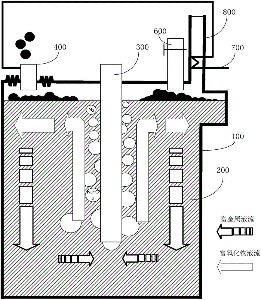
[0082] In this example, a liquid metal gasification furnace is used, copper-zinc alloy is used as the metal medium, graphite is used as the raw material, carbon dioxide and water vapor with a volume ratio of 2:1 are used as the gasification agent, and bauxite is used as the slagging agent. Preparation of synthesis gas, wherein, the schematic diagram of the structure of the gasifier is as follows figure 1 As shown, the molten pool 200 is a deep metal molten pool, and the air pipeline 300 is extended to the bottom of the deep metal molten pool. After the molten pool is deepened, the oxygen in the air can fully react with the liquid metal, and the gaseous oxygen and carbon raw materials are isolated. The contact between the carbon raw material gasification intermediate product and the product gas ensures the safe operation of the gasifier. The method of using the gasifier to prepare synthesis gas is as follows:

[0083] (1) The copper-zinc alloy is smelted by using the melting po...


PUM


Abstract

The invention discloses a gasifier and method for conducting gasification treatment on carbon-bearing raw materials. The gasifier comprises a shell, a smelting pool, an air pipeline and a spray gun, wherein a smelting space is defined by the shell, the smelting pool is arranged at the bottom of the smelting space and used for smelting metal raw materials so as to obtain molten metal, the air pipeline is arranged on the shell, extends into the smelting pool and is used for providing air for the smelting pool so as to utilize the air to conduct oxidation treatment on the molten metal and obtain molten metal oxides, and the spray gun is arranged on the shell, extends into the smelting space and is used for providing the carbon-bearing raw materials and gasifying agents for the smelting space, so that the carbon-bearing raw materials make contact with the gasifying agents, the molten metal oxides and the molten metal, and synthesis gas of hydrogen and carbon monoxide is obtained. According to the gasifier, the density difference of metal and the metal oxides is utilized to serve as driving force, a high-temperature metal circulation pump which is high in price is not needed, and natural circulation of bed materials in the gasifier can be achieved.

Description

technical field [0001] The invention relates to the field of chemical industry, in particular to a gasification furnace and a method for gasifying raw materials containing carbon. Background technique [0002] my country's local oil and gas resources are relatively scarce, while coal resources are relatively rich. Converting solid carbon fuels represented by coal and biomass into clean gaseous fuels or chemical synthetic fuels is an energy utilization technology route that is in line with my country's national conditions: it not only conforms to the actual natural conditions of our country, but also can effectively alleviate and solve the growing problems in the process of economic development. prominent environmental issues. [0003] The liquid metal gasifier uses liquid metal as the medium in the furnace. This gasifier has the following advantages: [0004] The temperature is easy to control, and liquid metal is a good conductor of heat, which can supply the heat released...

Claims


Application Information

Patent Timeline
IPC IPC(8): C10J3/57C10J3/46C10J3/48
Inventor 史翊翔曹天宇张格培蔡宁生
Owner TSINGHUA UNIV
Why Eureka
Try Eureka