
Rotor engine

A rotary engine and engine technology, applied in combustion engines, machines/engines, internal combustion piston engines, etc., can solve the problems of low work efficiency, large kinetic energy loss, and difficulty in achieving high-speed rotation, so as to improve work efficiency, facilitate combustion, reduce The effect of gas resistance

Active Publication Date: 2015-12-16
袁政
View PDF7 Cites 2 Cited by
  • Summary
  • Abstract
  • Description
  • Claims
  • Application Information

AI Technical Summary

Problems solved by technology

[0002] The traditional engine is a reciprocating piston engine, and its compression stroke, combustion stroke and expansion stroke are all carried out in a single cylinder, so it has the defect of excessive kinetic energy loss, making it difficult to achieve high-speed rotation and relatively low output power
In addition, during the working process of the traditional reciprocating piston engine, a large interaction force is generated between the piston and the crankshaft, which requires the piston and the crankshaft to have high strength. Therefore, it is necessary to increase the size of the piston, crankshaft and cylinder To make up for its lack of strength, which leads to a relatively large volume of the entire engine
[0003] General rotary engines can overcome the above-mentioned defects of reciprocating piston engines, but current rotary engines all have defects such as poor structural reliability and low work efficiency, such as the novel rotary engine disclosed in the patent document CN103899413A, whose The reset of the rocking piston is realized by the elastic element. Due to the high speed of the rotary engine, the elastic element is prone to damage or failure when the rocking piston swings rapidly. Moreover, in this new type of rotary engine, in order to prevent the combustion chamber from generating The gas recoils into the intake passage of the combustion chamber, and a check valve is installed in the intake passage of the combustion chamber. Due to the large resistance of the check valve, the working efficiency of the rotary engine will be reduced. Moreover, the check valve passes through quickly And it is easy to damage after repeated on-off

Method used


Image

  • Rotor engine
  • Rotor engine
  • Rotor engine

Examples


Embodiment Construction

[0040] Below, in conjunction with accompanying drawing and specific embodiment, the present invention is described further:

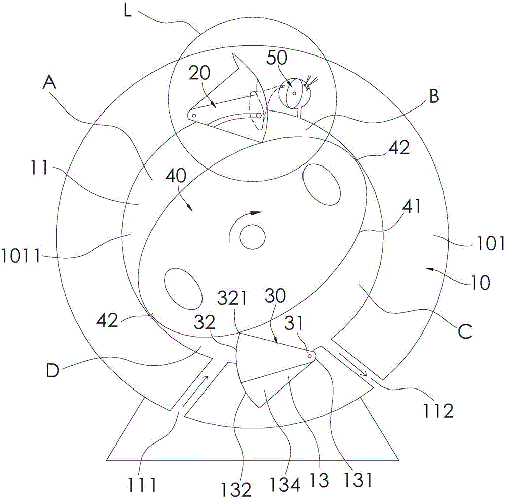
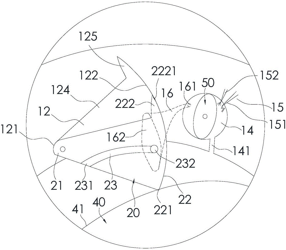
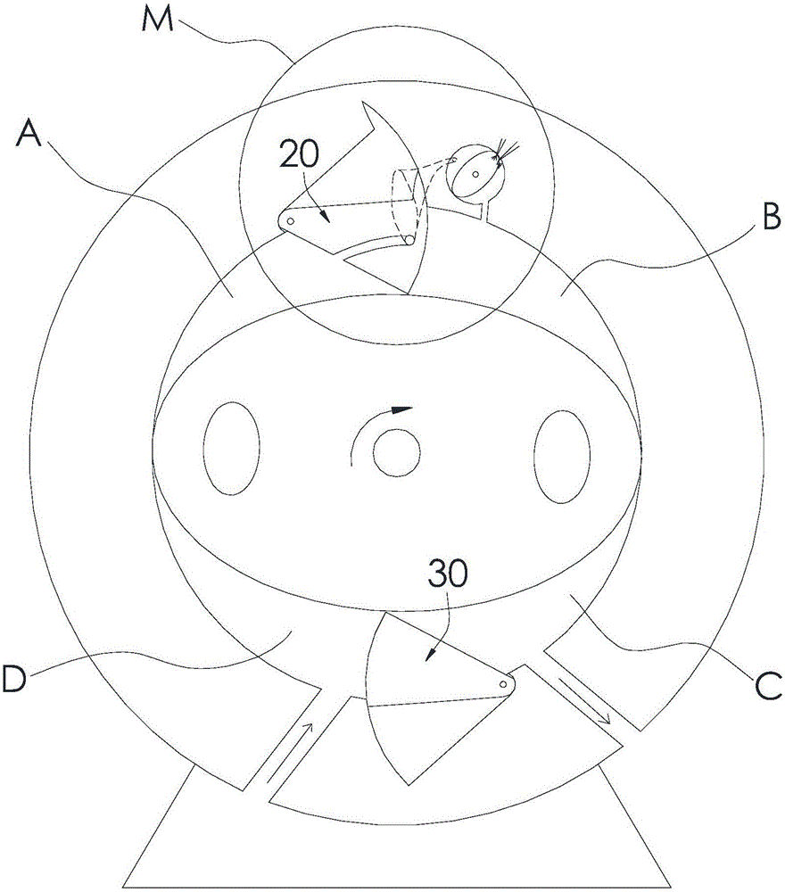
[0041] Such as Figure 1 to Figure 7 As shown, the rotary engine of the present invention includes a casing 10 , a first rocking piston 20 , a second rocking piston 30 , an engine rotor 40 and a combustion chamber rotor 50 . A main chamber 11 is formed inside the housing 10, a first piston groove 12 and a second piston groove 13 are provided on the side wall of the main chamber 11, and the first piston groove 12 and the second piston groove 13 are arranged along the main chamber. 11 is distributed symmetrically to the center, and the two ends of the first piston groove 12 are respectively provided with a first pivot joint 121 and a first sliding arc surface 122, and one side of the first piston groove 12 is provided with a second One opening, the two ends of the second piston groove 13 are respectively provided with a second pivot joint 131 and a secon...


PUM


Abstract

The invention discloses a rotor engine. The rotor engine comprises a casing, a first swing piston, a second swing piston, an engine rotor and a combustion chamber rotor, wherein a main chamber is formed at the inner part of the casing; a first piston groove and a second piston groove are formed in the side wall of the main chamber; the first swing piston comprises a first rotating part in rotating cooperation with a first pivoting part, and a first sliding part in airtight and sliding cooperation with a first cambered sliding surface; the second swing piston comprises a second rotating part in rotating cooperation with a second pivoting part, and a second sliding part in airtight and sliding cooperation with a second cambered sliding surface; the engine rotor can be mounted in the main chamber in a rotatable manner, and the center of the main chamber is positioned on a rotating shaft of the engine rotor; the combustion chamber rotor can be mounted in a combustion chamber in a rotatable manner, and the center of the combustion chamber is positioned on a rotating shaft of the combustion chamber rotor. The rotor engine disclosed by the invention is good in structural reliability, and high in working efficiency.

Description

technical field [0001] The invention relates to a rotary engine. Background technique [0002] The traditional engine is a reciprocating piston engine, and its compression stroke, combustion stroke, and expansion stroke are all carried out in a single cylinder. Therefore, it has the defect of excessive kinetic energy loss, making it difficult to achieve high-speed rotation and relatively low output power. In addition, during the working process of the traditional reciprocating piston engine, a large interaction force is generated between the piston and the crankshaft, which requires the piston and the crankshaft to have high strength. Therefore, it is necessary to increase the size of the piston, crankshaft and cylinder To make up for its lack of strength, this leads to a relatively large volume of the entire engine. [0003] General rotary engines can overcome the above-mentioned defects of reciprocating piston engines, but current rotary engines all have defects such as p...

Claims


Application Information

Patent Timeline
IPC IPC(8): F02B55/08F02B55/14F02B55/16F02B55/02
Inventor 袁政
Owner 袁政
Learn More