
Novel rotor engine

A rotor engine and rotor technology, applied in the direction of combustion engine, machine/engine, internal combustion piston engine, etc., can solve the problem that the applicability of the technical solution does not exceed the comprehensive performance of the piston engine, and the transmission system and gas distribution system of the piston engine are complex and difficult to obtain Reliability and durability and other issues, to achieve the effect of low noise, complementary power, and simple mechanism

Inactive Publication Date: 2015-12-16
李状
View PDF0 Cites 1 Cited by
  • Summary
  • Abstract
  • Description
  • Claims
  • Application Information

AI Technical Summary

Problems solved by technology

First, when the piston does work, the piston will constantly rub against the cylinder wall, thereby generating a large amount of heat. In order to reduce the temperature, people have adopted various methods, but due to its unique technical characteristics, it is difficult to make an immediate breakthrough, and this process also requires Second, the piston moves in a straight line, and the linear motion is converted into rotary motion through machinery. This process itself not only consumes a part of energy, but also inevitably produces noise; third, in order to increase the power, the cylinder must be increased. Quantity (currently commonly used are V-shaped arrangement, horizontally opposed arrangement, star arrangement, etc.
), although the power of each cylinder can complement each other through the connection of the crankshaft, the independence of the cylinder blocks takes up a lot of space, making it difficult to control the weight and volume in a small range; and the stability is greatly reduced
Fourth, the piston engine transmission system and gas distribution system are more complicated, and more parts make it difficult to achieve ideal reliability and durability
[0003] In order to solve the above technical bottlenecks, people have designed many solutions, such as Wankel rotary engine, Quasi rotary engine, etc., but the applicability of the technical solutions has not surpassed the comprehensive performance of the piston engine

Method used


Image

  • Novel rotor engine
  • Novel rotor engine
  • Novel rotor engine

Examples


Embodiment Construction

[0018] 1. Mechanical structure

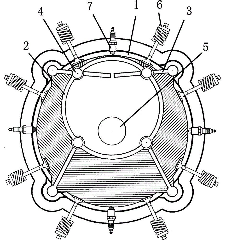
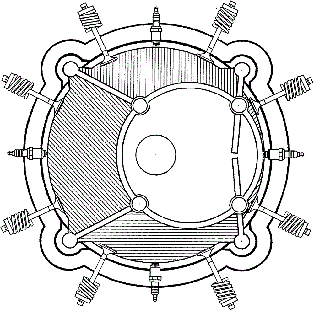
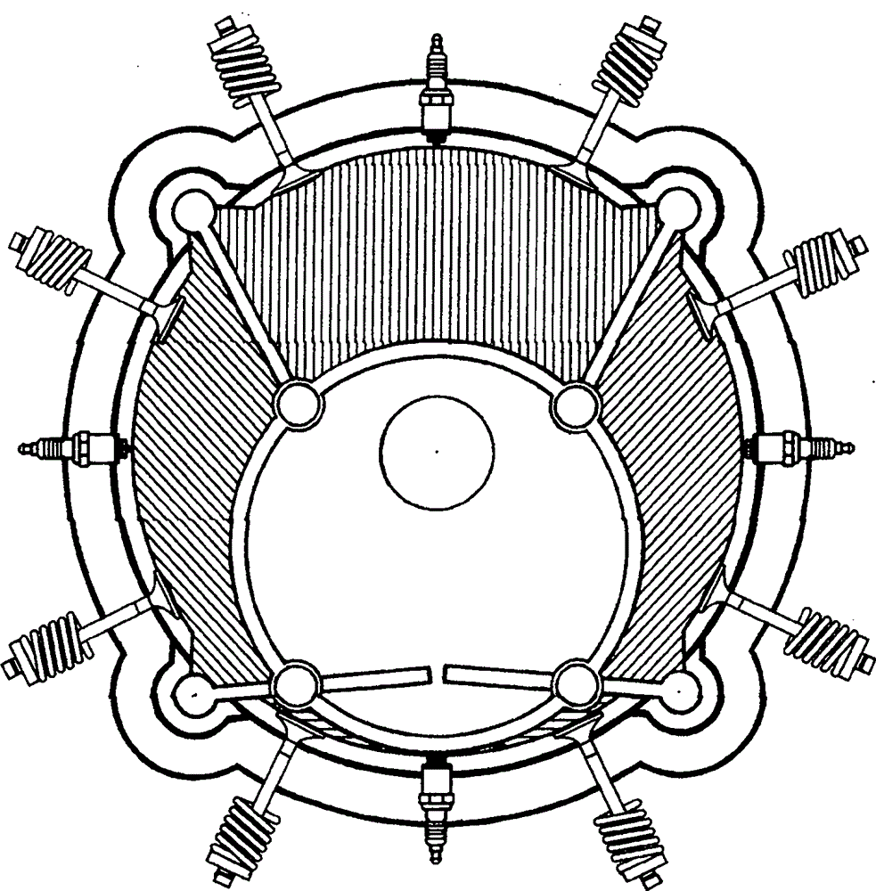
[0019] figure 1 —— Figure 8 It shows 4 combustion chambers in a cylinder, each combustion chamber has a complete four-stroke space change process and the movement of the rotor, as well as the distribution of spark plugs and intake and exhaust mechanisms; Figure 9 Shows the structural shape of the rotor collar (ring type, hollow hole in the middle); Figure 10 The structure and shape of the output shaft turntable are shown; Figure 11 It shows the state of the rotor collar embedded in the output shaft turntable; Figure 12 Another way to show the combination of the isolation plate, the rotor and the cylinder as claimed in claim 8; Figure 13 A perspective view showing the distribution and combination of the main mechanisms of the engine; Figure 14 A three-dimensional view showing the combination of the rotor, the isolation plate, and the airtight bearing; Figure 15 Another way of combining the isolation plate and the rotor described i...


PUM


Abstract

The invention relates to a novel rotor engine. The rotor engine mainly comprises the components of a cylindrical inner cylinder wall (1), a rotor (2), an isolating board (3), a rotor lantern ring (8), an output shaft turntable (10), an airtight roller (4), a power output shaft (5), an air suction and exhausting device (6) and a spark plug (7). According to the rotor engine, a piston connecting rod and a crankshaft of a piston engine are abandoned; a combustion pushing force directly pushes the output shaft turntable to rotate; all combustion chambers are arranged in a same cylinder, thereby saving space and greatly reducing the size of the engine; all combustion chambers are distributed around the rotor, thereby generating a pushing force one by one for realizing a circular motion, enlarging a power, compensating the power and realizing smooth operation. A relatively short cylinder compression stroke is realized, thereby realizing a relatively small cylinder diameter. A complicated air suction and exhausting brake mechanism can be abandoned, and gear transmission is utilized. As the rotor does not directly contact with the cylinder wall and only rolls in the airtight roller by means of the isolating board, an abrasion is greatly reduced and a power loss rate is reduced. Furthermore the novel rotor engine has advantages of smooth operation, reliable power, high durability, small noise, simple structure, easy manufacture, easy detachment and easy maintenance.

Description

technical field [0001] The invention relates to a novel rotary engine. Background technique: [0002] At present, the general mechanical power source generally adopts a reciprocating piston engine. As we all know, the reciprocating piston engine uses the pressure of fuel combustion and expansion on the top of the piston to make the piston move in a straight line, and then drives the crankshaft to make a circular motion through the connecting rod. This classic design has been generally recognized by people after a long period of testing, but it also has its inherent defects. First, when the piston does work, the piston will constantly rub against the cylinder wall, thereby generating a large amount of heat. In order to reduce the temperature, people have adopted various methods, but due to its unique technical characteristics, it is difficult to make an immediate breakthrough, and this process also requires Second, the piston moves in a straight line, and the linear motion ...

Claims


Application Information

Patent Timeline
Patent Type & Authority Applications(China)
IPC IPC(8): F02B53/00F02B55/02F02B55/08F02B53/02
CPCY02T10/12
Inventor 李状
Owner 李状
Learn More