
Segment difference grinding machine

A grinding machine and rough grinding technology, applied in the direction of grinding machine, grinding bed, grinding machine parts, etc., can solve the problems of low work efficiency and precision, affecting processing precision, small moving stroke, etc., to reduce swing, The effect of improving machining accuracy and increasing distance

Active Publication Date: 2015-12-16
广东豪特曼机床股份有限公司
View PDF8 Cites 2 Cited by
  • Summary
  • Abstract
  • Description
  • Claims
  • Application Information

AI Technical Summary

Problems solved by technology

At present, there is only one layer of guide rails in the working head frame of the step grinding machine that is common in the market. The moving stroke is relatively small. When grinding a long workpiece, there is no pressing device at the front end of the workpiece, which is prone to rotation and swing, which affects the processing. precision
Moreover, the grinding wheel head works with a single grinding wheel. If rough grinding and fine grinding of the workpiece are required, different grinding wheels must be installed, and the work efficiency and precision are not high.

Method used


Image

  • Segment difference grinding machine
  • Segment difference grinding machine

Examples


Embodiment Construction

[0014] The present invention will be further described in detail below in conjunction with the accompanying drawings and specific embodiments.

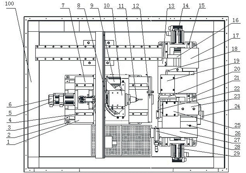
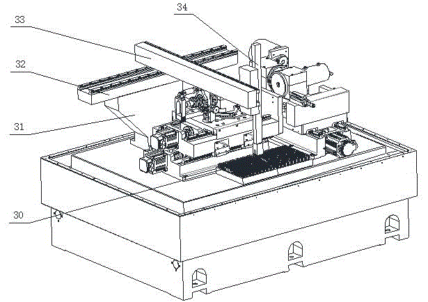
[0015] Such as Figure 1-2 The step grinding machine shown includes a machine tool body 100, and a material tray 30, a working head assembly, a grinding wheel assembly and a manipulator 34 assembly that are all installed on the machine tool body 100. The manipulator 34 assembly is located above the working head assembly and the grinding wheel assembly. The working head assembly includes Saddle 1, base 2, first guide rail 3, first screw mandrel, first servo motor 6, pressing device 12, working head slide plate 7, second guide rail 4, second screw mandrel, second servo motor 5, first Three servo motors 9, spindle fixing seat 10, working head spindle 8 and workpiece clamping device 11, the base 2 is fixed on the machine tool body 100, the first guide rail 3 is fixed on the base 2 along the transverse direction, the saddle 1 is slidably m...


PUM


Abstract

The invention discloses a segment difference grinding machine. The segment difference grinding machine comprises a machine tool body, and a material plate, a working head assembly, a grinding wheel assembly and a mechanical hand assembly which are all arranged on the machine tool body. The mechanical hand assembly is located above the working head assembly and the grinding wheel assembly. The working head assembly comprises a saddle, a base, a first guide rail, a first lead screw, a first servo motor, a material pressing device, a working head sliding plate, a second guide rail, a second lead screw, a second servo motor, a third servo motor, a main shaft fixing base, a working head main shaft and a workpiece clamping device. The base is fixed to the machine tool body. The first guide rail is transversely fixed to the base. The saddle is in slide fit with the first guide rail. The first servo motor is fixed to the base and connected with the first lead screw in a butt joint mode. The first lead screw is matched with the saddle in a threaded mode. The second guide rail is fixed to the saddle and parallel to the first guide rail. The working head sliding plate is in slide fit with the second guide rail. The movement distance of the working head assembly is large. Rotating and swinging of workpieces are small, and the machining efficiency and accuracy are high.

Description

technical field [0001] The present invention relates to a grinding machine, in particular to a step grinding machine. Background technique [0002] The step difference grinder is a forming machine used to form the step difference outer diameter of the workpiece. At present, there is only one layer of guide rails in the working head frame of the step grinding machine that is common in the market. The moving stroke is relatively small. When grinding a long workpiece, there is no pressing device at the front end of the workpiece, which is prone to rotation and swing, which affects the processing. precision. Moreover, the emery wheel head works as a single emery wheel, and if the rough grinding and fine grinding of the workpiece are required, different emery wheels must be replaced to complete, and the work efficiency and precision are not high. Contents of the invention [0003] In order to overcome the deficiencies of the prior art, the object of the present invention is t...

Claims


Application Information

Patent Timeline
Patent Type & Authority Applications(China)
IPC IPC(8): B24B27/00B24B41/02B24B47/12B25J11/00
CPCB24B27/0076B24B41/02B24B47/12B25J11/0065
Inventor 吴光明曾俊刘太明
Owner 广东豪特曼机床股份有限公司
Learn More