
Key switch, keyboard and key-switch assembling jig

a key switch and key-switch technology, which is applied in the direction of static indicating devices, contact mechanisms, instruments, etc., can solve the problems of inexperienced operators, difficult configuration, impaired etc., and achieve stable key-entry operability of the key top, increase the amount of vertical movement, and reduce the height dimension of the key switch

Active Publication Date: 2006-11-21
FUJITSU COMPONENENT LTD
View PDF18 Cites 35 Cited by
  • Summary
  • Abstract
  • Description
  • Claims
  • Application Information

AI Technical Summary

Benefits of technology

The present invention provides a key switch that can be subjected to a key-entry operation with increased stroke of the key top and decreased height dimension of the key switch. This allows for a low-profile keyboard with excellent operability and reduces fatigue of the operator. The key switch includes a support plate, a key top, a pair of link members interlocked to each other to support the key top, and a switch mechanism including a membrane switch sheet placed on the support plate. The link members have sliding parts that are engaged with the support plate through guide holes in the membrane switch sheet. The key switch also includes an assembling jig and a keyboard with the key switches arranged in a certain arrangement. The technical effects of the invention include increased usability of the key switch, reduced fatigue of the operator, and improved assembly of the key switch.

Problems solved by technology

As a result, the stability of the interlocking movement of the link members (especially, of the sliding motion of the sliding part) may be degraded, and thus the key-entry operability of the key top may be impaired.
This configuration may be difficult, especially for an inexperienced operator.
Further, the plural key tops having substantially same size and different shape are used in the above keyboard, so that the assembling process of the keyboard may become complicated and thus may lead to increase in the manufacturing cost.
Also, the assembling process of the key switch has often been performed manually, and it becomes difficult to manually assemble the small-sized link members accurately on the support plate, without causing damage or loss of the link members.

Method used


Image

  • Key switch, keyboard and key-switch assembling jig
  • Key switch, keyboard and key-switch assembling jig
  • Key switch, keyboard and key-switch assembling jig

Examples


first embodiment

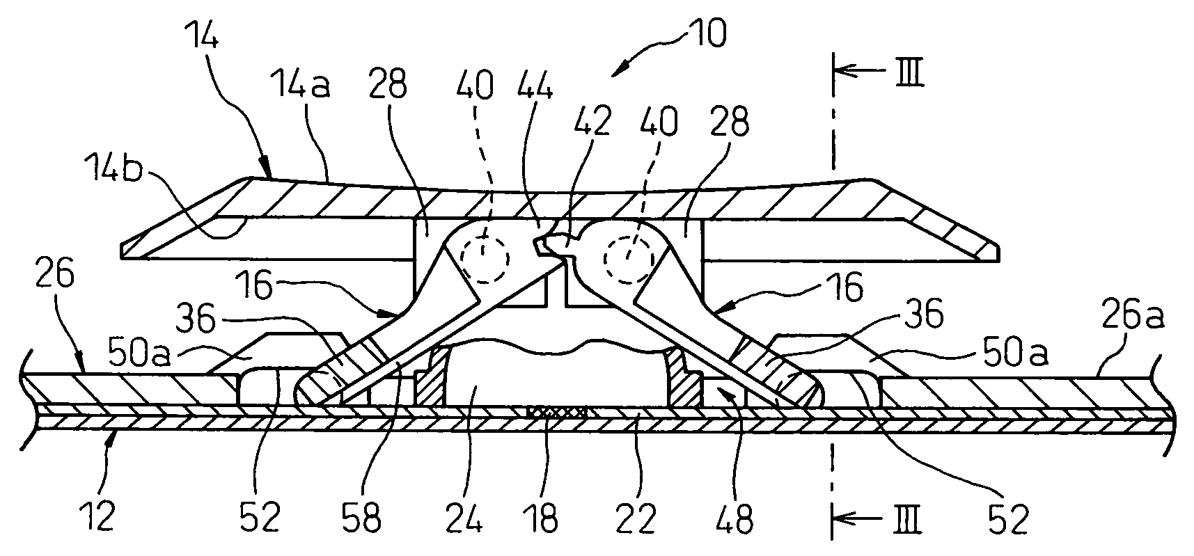
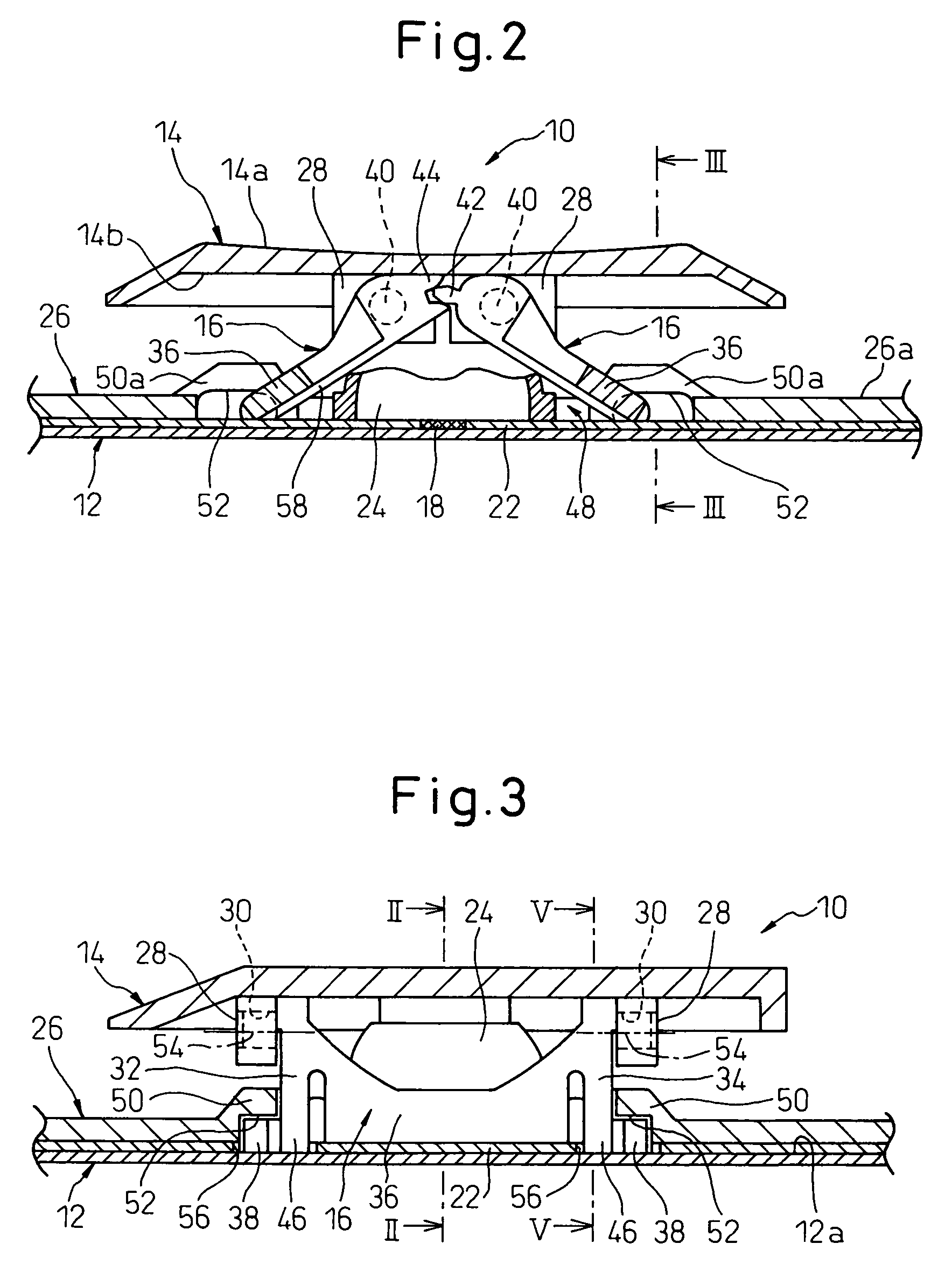
[0066]Referring to the drawings, FIG. 1 is an exploded perspective view showing a key switch 10 according to the present invention, FIGS. 2 and 3 are sectional views showing the assembled key switch 10 in an inoperative state, FIG. 4 is an enlarged perspective view showing one component of the key switch 10, and FIG. 5 is a sectional view showing the assembled key switch 10 in a depressed or operative state.

[0067]As shown in FIG. 1, a key switch 10 includes a support plate 12, a key top 14 arranged above the support plate 12, a pair of link members 16 interlocked to each other to support the key top 14 above the support plate 12 and direct the key top 14 in a vertical or up-and-down direction, and a switch mechanism 20 capable of opening and closing a contact section 18 (FIG. 2) of an electric circuit in accordance with the vertical or up-and-down movement of the key top 14. The switch mechanism 20 includes a membrane switch sheet 22 carrying the contact section 18 at a position cor...

second embodiment

[0101]Incidentally, the key switch 60 according to the present invention and described with reference to FIGS. 6 to 9B has an exemplary configuration in which the support plate 62 is formed of a sheet metal material. In this configuration, two pairs of guide sections 64 are formed integrally with the remaining portion of the support plate 62 at desired locations on the support plate 62, preferably by a lancing process (or a punching and bending process) using a press machine. This configuration is advantageous in a point that sufficient rigidity can be ensured even with a thin support plate 62.

[0102]The support plate 62 is preferably formed from aluminum or magnesium alloy in order to reduce the weight of the key switch 60. Magnesium alloy is particularly suitable as the material for the support plate 62 of the key switch 60 because of its light weight and high rigidity. Due to its high rigidity, however, magnesium alloy tends to be difficult to use in forming the guide sections 64 ...


PUM


Abstract

A key switch used for a keyboard incorporated as an input device in electronic equipment. The key switch includes a support plate; a key top arranged above the support plate; a pair of link members interlocked to each other to support the key top above the support plate and direct the key top in a vertical direction; and a switch mechanism capable of opening and closing a contact section of an electric circuit in accordance with a vertical movement of the key top. The switch mechanism includes a membrane switch sheet carrying the contact section at a position corresponding to the key top and placed on the support plate. Each of the link members includes a sliding part slidably engaged with the support plate. The membrane switch sheet is provided with a through-hole in a region where the sliding part of each link member is engaged with the support plate, the sliding part of the link member being slidably placed on the support plate through the through-hole in the membrane switch sheet.

Description

BACKGROUND OF THE INVENTION[0001]1. Field of the Invention[0002]The present invention relates generally to a switch configuration for key-entry operation and, more particularly, to a key-entry switch device (hereinafter referred to as a key switch) preferably used for a keyboard incorporated, as an input device, in electronic equipment. The present invention also relates to a keyboard provided with a plurality of key switches. The present invention further relates to an assembling jig usable for assembling a key switch.[0003]2. Description of the Related Art[0004]In a thinner or low-profile-type keyboard for a portable electronic apparatus, such as a notebook or palm-top personal computer, it is required to reduce the height of a key switch for a key-entry operation as well as to improve the operability of the key switch. The key switch usable in the low-profile keyboard generally includes a support plate (e.g., a metal sheet, a bottom panel of a keyboard, etc.), a key top arranged ...

Claims


Application Information

Patent Timeline
Patent Type & Authority Patents(United States)
IPC IPC(8): H01H9/00
CPCH01H3/122H01H3/125H01H11/00H01H2217/00H01H2217/024H01H2229/00
Inventor NISHINO, TAKESHINAKAMURA, SHUJITAKEMAE, AKIHIKO
Owner FUJITSU COMPONENENT LTD
Learn More