
3-D channel gas heat exchanger

A heat exchanger, 3-D technology, applied in the direction of heat exchanger fixation, heat exchange equipment, indirect heat exchangers, etc., can solve the problems of insulation box size increase, heavy weight, fatigue cracking, etc., and achieve the improvement of blockage Effect

Active Publication Date: 2015-11-25
CORHEX CORP
View PDF5 Cites 5 Cited by
  • Summary
  • Abstract
  • Description
  • Claims
  • Application Information

AI Technical Summary

Problems solved by technology

[0007] Existing heat exchangers such as shell and tube heat exchangers or coil heat exchangers are reported to be unsuitable for use in high pressure LNG vaporizers for natural gas powered vessels due to the following problems
[0008] First, in shell and tube heat exchangers designed and manufactured for use in high pressure and very low temperature environments, due to the difference between the heat capacity of the thick tube sheets used to withstand high pressure and the relatively thin tubes, fatigue cracking likely to occur at the joint
[0009] Second, shell-and-tube heat exchangers, etc. inevitably rely on the length of the tubes in order to increase the heating area, and require large size and heavy weight due to low compactness
[0010] Third, due to the large size, the size of the insulation box used to block the heat inlet and outlet is further increased, and thus the cost and the installation space in the ship are greatly increased
For this, the corresponding ship or factory must be stopped, but due to the nature of the system, it is difficult to stop the entire system

Method used


Image

  • 3-D channel gas heat exchanger
  • 3-D channel gas heat exchanger
  • 3-D channel gas heat exchanger

Examples


Embodiment Construction

[0044] Hereinafter, exemplary embodiments of the present invention will be described in detail with reference to the accompanying drawings. In describing the principle of operation of the exemplary embodiments of the present invention, however, when it is determined that a detailed description of a relevant function or configuration makes the subject matter of the present invention unnecessarily unclear, the detailed description will be omitted.

[0045] Also, the same reference numerals are used throughout the drawings to indicate elements having similar functions and operations. Throughout the specification, when it is described that one element is coupled with one element, the one element may be directly coupled with the other element or may be indirectly coupled with the other element through a third element.

[0046] Also, when a recited element includes any element, it means that the element does not exclude other elements, but may also include another element, unless st...


PUM

PropertyMeasurementUnit
Lengthaaaaaaaaaa
Lengthaaaaaaaaaa
Diameteraaaaaaaaaa

Abstract

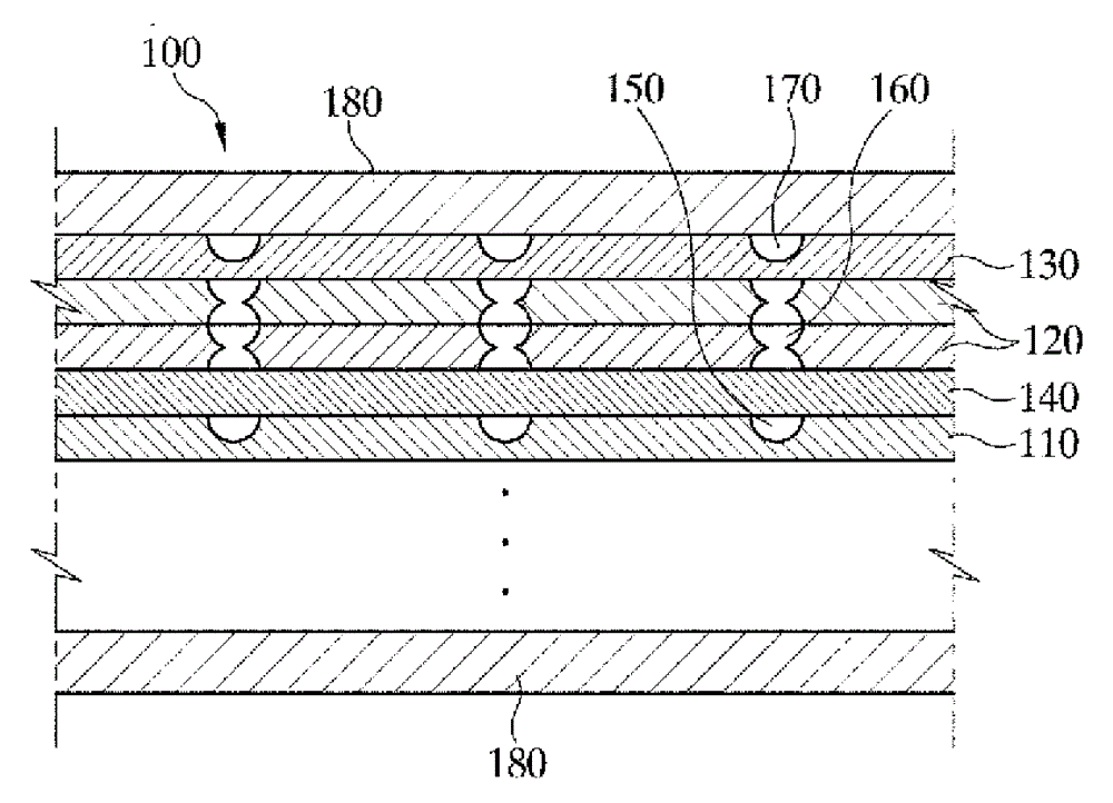
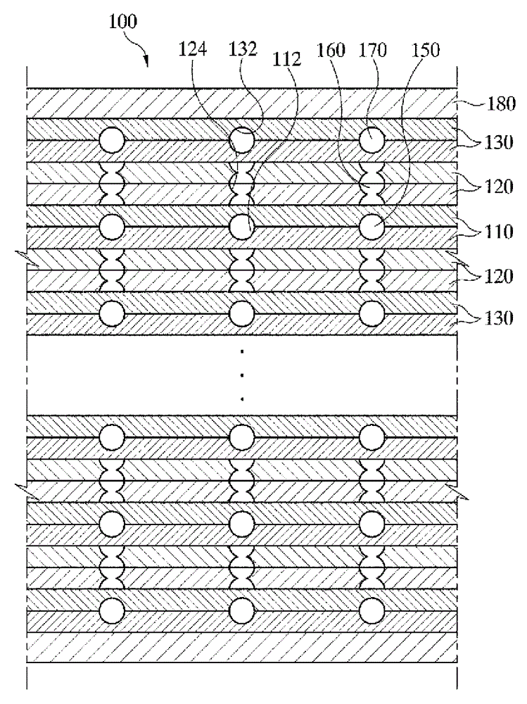
The present invention relates to a 3-d channel gas heat exchanger. The 3-D channel gas heat exchanger includes a plurality of heat exchange plates configured to have heating surface units for exchanging heat formed on one sides of the heat exchange plates and a plurality of passages and that are formed in between the plurality of heat exchange plates and wherein the plurality of passages comprise, first passages configured to convey a first fluid having a first temperature through the first passages, second passages configured to convey a second fluid through the second passages for transferring heat to the first fluid having the first temperature and third passages configured to prevent freezing in the second passages by transferring heat to at least some of the second passages when a temperature (T) of the second fluid is below a predetermined temperature value (Tref).

Description

technical field [0001] The present invention relates to a three-dimensional (3-D) pass-through gas heat exchanger made by performing diffusion bonding on a metal plate in which photolithography is used and then the top plate is welded to the metal plate Fine channels are formed in order to vaporize LNG or cool process gas with high temperature for chemical processes. [0002] More specifically, the present invention relates to a 3-D passage gas heat exchanger, which can be used in an environment of extreme low temperature or high temperature and high pressure, has a much smaller volume than existing shell and tube heat exchangers, and can make the flow Freeze plugging phenomenon to or from heat sources in passages or fatigue cracking phenomena due to differences in temperature and pressure are minimized, and it has high heat transfer coefficient and improved pressure resistance properties by forced separation and mixing. Background technique [0003] The International Marit...

Claims


Application Information

Patent Timeline
IPC IPC(8): F02M21/02F02M21/06F02M31/16B63H21/38
CPCF28D9/0093B63H21/38F02M21/0215F02M21/06F28D9/0037F28D2021/0064F28F19/006F28F2275/061Y02T10/32F28F23/02B63B25/16F02M21/0245F02M31/10F02M31/18F17C9/00F17C2265/05F17C2265/066F17C2270/0105F17C2227/0309Y02T70/5218Y02T10/30
Inventor Y-J.蔡
Owner CORHEX CORP
Learn More