Heat-conducting structure and heat-dissipation device

A heat-conducting structure and heat-dissipating device technology, applied in the direction of modification, heat transfer modification, indirect heat exchanger, etc. through conduction heat transfer, which can solve the problem of large radiator volume

Active Publication Date: 2015-11-25
JIANGSU CNANO TECHNOLOGY CO LTD
View PDF4 Cites 18 Cited by
  • Summary
  • Abstract
  • Description
  • Claims
  • Application Information

AI Technical Summary

Problems solved by technology

[0004] However, for the above-mentioned heat dissipation device, the heat sink is too large in size and cannot meet the light and thin requirements of today's thin and thin electronic products.

Method used


Image

  • Heat-conducting structure and heat-dissipation device
  • Heat-conducting structure and heat-dissipation device
  • Heat-conducting structure and heat-dissipation device

Examples


Embodiment Construction

[0028] The heat conduction structure and heat dissipation device according to preferred embodiments of the present invention will be described below with reference to related drawings, wherein the same elements will be described with the same reference symbols.

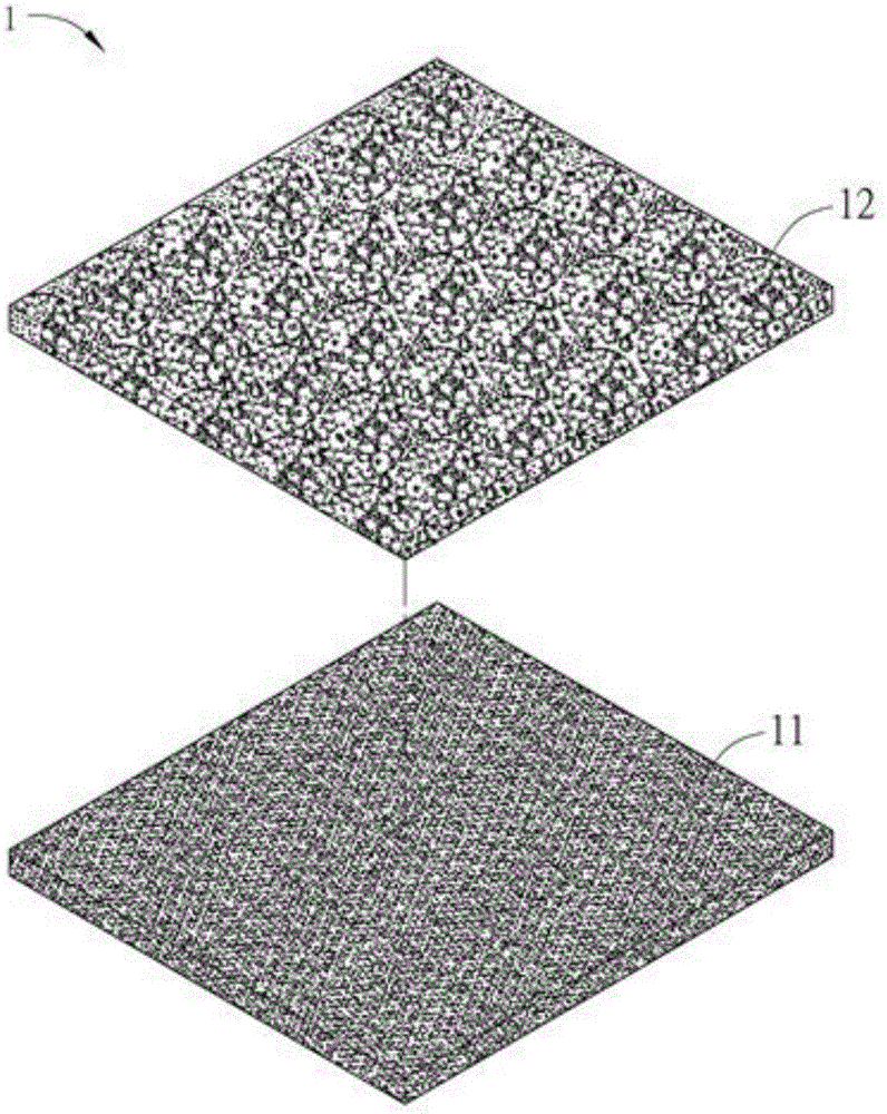
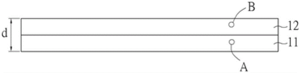
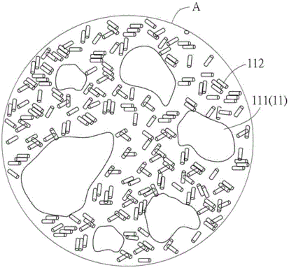
[0029] Please refer to Figure 1A to Figure 1D As shown, among them, Figure 1A and Figure 1B are respectively an exploded schematic diagram and a schematic side view of a heat conduction structure 1 in a preferred embodiment of the present invention, and Figure 1C and Figure 1D respectively Figure 1B The enlarged schematic diagram of area A and area B of . hereby, Figure 1C and Figure 1D They are for illustration only and are not drawn to scale of actual components.

[0030] The heat conduction structure 1 can quickly lead out the heat energy generated by the heat source (such as an electronic component), and includes a first heat conduction layer 11 and a second heat conduction layer 12, and the first he...


PUM

PropertyMeasurementUnit
thicknessaaaaaaaaaa
particle diameteraaaaaaaaaa

Abstract

The invention discloses a heat-conducting structure and a heat-dissipation device. The heat-conducting structure comprises a first heat-conducting layer and a second heat-conducting layer, wherein the first heat-conducting layer comprises a graphene material and first carbon nanotubes; the first carbon nanotubes are dispersed into the graphene material; the second heat-conducting layer is stacked on the first heat-conducting layer and comprises a porous material and second carbon nanotubes; and the second carbon nanotubes are dispersed into the porous material. The invention further discloses the heat-dissipation device. The heat-dissipation device comprises the heat-conducting structure and a heat-dissipation structure; the heat-conducting structure contacts a heat source; and the heat-dissipation structure is connected with the heat-conducting structure. The heat-conducting structure and the heat-dissipation device disclosed by the invention have the thinning characteristics, and conform to the lightweight requirements of current thin electronic products.

Description

technical field [0001] The invention relates to a heat conduction structure and a heat dissipation device, in particular to a thinned heat conduction structure and heat dissipation device. Background technique [0002] With the development of science and technology, for the design and development of electronic devices, thinness and high performance are always given priority. In the case of high-speed calculation, the electronic components of the electronic device will inevitably generate more heat than the previous electronic components, but because the high temperature working environment will not only affect the characteristics of the electronic components, but the high temperature may cause electronic permanent damage to the component. Therefore, in order to meet the trend of thinner products of electronic devices, thinner heat sinks have become one of the indispensable and important equipment in current electronic devices. [0003] The known cooling device generally in...

Claims


Application Information

Patent Timeline
Patent Type & Authority Applications(China)
IPC IPC(8): H05K7/20
CPCF28D2021/0029F28F13/003F28F21/02H01L23/373H01L23/3731H01L23/3736H01L23/3737H05K7/20181H05K7/20481H05K7/20172H05K7/20336H05K7/2039F28F3/00H05K7/20136
Inventor 蔡韋政杨智偉郑涛毛鸥张美杰
Owner JIANGSU CNANO TECHNOLOGY CO LTD
Why Eureka
Try Eureka