
Double-freedom degree rotation device driven by ultrasonic motor

An ultrasonic motor and rotating device technology, applied in electromechanical devices, generators/motors, electric components, etc., can solve the problems of low driving accuracy, complex structure, large volume, etc., and achieve small size, compact overall structure, and high precision. Effect

Inactive Publication Date: 2015-11-25
HARBIN INST OF TECH
View PDF10 Cites 11 Cited by
  • Summary
  • Abstract
  • Description
  • Claims
  • Application Information

AI Technical Summary

Problems solved by technology

[0006] The present invention aims to solve the problems of the existing dual-degree-of-freedom rotating device with complex structure, large volume, heavy weight and low driving precision, and further provides a dual-degree-of-freedom rotating device driven by an ultrasonic motor

Method used


Image

  • Double-freedom degree rotation device driven by ultrasonic motor
  • Double-freedom degree rotation device driven by ultrasonic motor
  • Double-freedom degree rotation device driven by ultrasonic motor

Examples


specific Embodiment approach 1

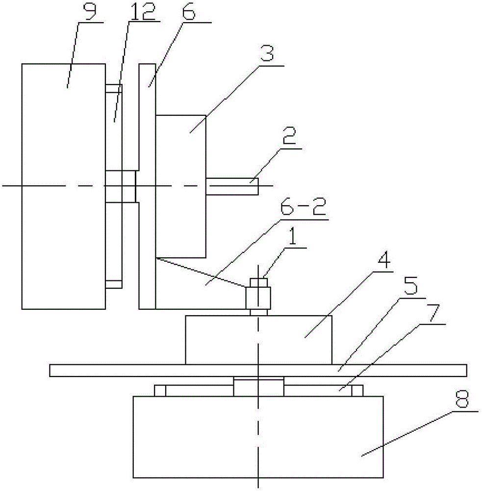
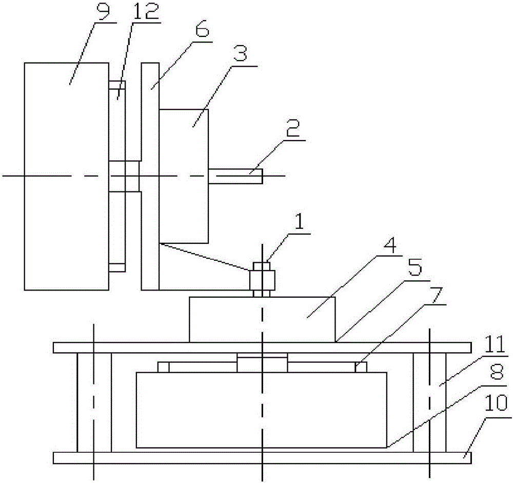
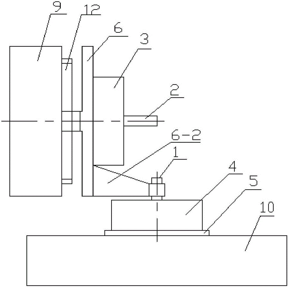
[0014] Specific implementation mode one: combine Figure 1-Figure 5 Explain that a two-degree-of-freedom rotating device driven by an ultrasonic motor in this embodiment includes a supine motion mechanism and an azimuth motion mechanism;

[0015] The azimuth movement mechanism includes an azimuth ultrasonic motor 4, an azimuth ultrasonic motor seat 5 and an azimuth encoder 8;

[0016] The supine motion mechanism includes a pitching ultrasonic motor 3, a pitching ultrasonic motor seat 6 and a pitching encoder 9;

[0017] The azimuth ultrasonic motor 4 is installed on the azimuth ultrasonic motor base 5, the shaft of the azimuth encoder 8 is coaxially connected to the motor shaft of the azimuth ultrasonic motor 4, and the output shaft of the azimuth ultrasonic motor 4 is connected to the pitch ultrasonic motor base 6;

[0018] The pitching ultrasonic motor 3 is installed on the pitching ultrasonic motor base 6, the shaft of the pitching encoder 9 is coaxially connected with the...

specific Embodiment approach 2

[0020] Specific implementation mode two: combination Figure 1-Figure 5 Note that the azimuth ultrasonic motor 4 in this embodiment is a traveling wave rotary ultrasonic motor or a standing wave rotary ultrasonic motor. Such a setting is small in size, light in weight, convenient and reliable in use, and meets actual needs. The load can rotate 360° around the output shaft of the azimuth ultrasonic motor 4, and the load can rotate ≥ 180° around the output shaft of the pitch ultrasonic motor 3. Others are the same as in the first embodiment.

specific Embodiment approach 3

[0021] Specific implementation mode three: combination Figure 1-Figure 5 Note that the pitching ultrasonic motor 3 of this embodiment is a traveling wave rotary ultrasonic motor or a standing wave rotary ultrasonic motor. Such a setting is small in size, light in weight, convenient and reliable in use, and meets actual needs. The load can rotate 360° around the output shaft of the azimuth ultrasonic motor 4, and the load can rotate ≥ 180° around the output shaft of the pitch ultrasonic motor 3. Others are the same as in the first or second embodiment.


PUM


Abstract

The invention discloses a double-freedom degree rotation device driven by an ultrasonic motor, relating to a device capable of achieving double freedom degrees and aiming to solve the problems of complicated structure, large volume, heavy weight and low driving accuracy of the double-freedom degree rotation device. The double-freedom degree rotation device comprises a supine movement mechanism and a direction movement mechanism, wherein the direction movement mechanism comprises a direction ultrasonic motor, a direction ultrasonic motor seat and a direction encoder; the supine movement mechanism comprises a pitching ultrasonic motor, a pitching ultrasonic motor seat and a pitching encoder; the direction ultrasonic motor is arranged on the direction ultrasonic motor seat; a shaft of a direction encoder and a motor shaft of the direction ultrasonic motor are coaxially arranged and connected; an output shaft of the direction ultrasonic motor is connected with the pitching ultrasonic motor seat; the pitching ultrasonic motor is arranged on the pitching ultrasonic motor seat; a shaft of the pitching encoder and a motor shaft of the pitching ultrasonic motor are coaxially arranged and connected; and an output shaft of the pitching ultrasonic motor is connected with a load. The double-freedom degree rotation device is used for driving the load.

Description

technical field [0001] The invention relates to a device capable of realizing double degrees of freedom, in particular to a novel high-precision rotating device with double degrees of freedom directly driven by an ultrasonic motor. Background technique [0002] In the existing patent No. "200820125881.X" "Double-degree-of-freedom precise rotation device": the base and the connecting seat of the rotating frame are connected by bearings, the driving device and the driving encoder are respectively connected to the rotating frame, and the driving device is Stepper motor plus harmonic reducer. The encoder is used in the device, which relatively improves the accuracy of the device; the disadvantages of the above devices are: large volume, heavy mass, and low precision. [0003] In the "A Spaceborne Precision Sun Pointing Mechanism" with the application number "201210278883.3", the combination of two structures, the azimuth rotation part and the pitch rotation part, is adopted. Th...

Claims


Application Information

Patent Timeline
Patent Type & Authority Applications(China)
IPC IPC(8): H02K7/10H02N2/10
Inventor 曲建俊陶小鹤刘德赟姚旗田昀王培明
Owner HARBIN INST OF TECH
Learn More