
A multi-layer nested conical X-ray grazing incidence optical lens

An optical lens and X-ray technology, applied in the field of space optics, can solve the problems of complex parabolic primary mirror and hyperboloid secondary mirror, reduce the total reflectivity of the optical lens, and difficult installation and adjustment, so as to increase the effective light-collecting area , Large effective light-collecting area and strong ability to resist stray light interference

Active Publication Date: 2017-12-22
BEIJING INST OF CONTROL ENG
View PDF6 Cites 0 Cited by
  • Summary
  • Abstract
  • Description
  • Claims
  • Application Information

AI Technical Summary

Problems solved by technology

[0004] The existing soft X-ray grazing incidence optical lens mostly adopts Wolter-I structure, which focuses the soft X-ray on the focal plane through the double reflection of the parabolic primary mirror and the hyperbolic secondary mirror. This structure is mainly suitable for soft X-ray targets source imaging, but the parabolic primary mirror and the hyperbolic secondary mirror have complex shapes and are difficult to process. The two reflections reduce the total reflectivity of the optical lens. There is a strict coupling relationship between the parabolic primary mirror and the hyperbolic secondary mirror. Accurate alignment can achieve the focus of soft X-rays, and the installation and adjustment are difficult
[0005] Another commonly used soft X-ray grazing incidence optical lens is a lobster eye structure. This optical lens works on the principle of lobster eye imaging and can achieve large field of view observation (tens to thousands of square degrees), but its large field of view The field will introduce more background noise, and the instantaneous effective area is small, which reduces the signal-to-noise ratio, and is only suitable for X-ray sky survey observation and monitoring

Method used


Image

  • A multi-layer nested conical X-ray grazing incidence optical lens
  • A multi-layer nested conical X-ray grazing incidence optical lens
  • A multi-layer nested conical X-ray grazing incidence optical lens

Examples


Embodiment

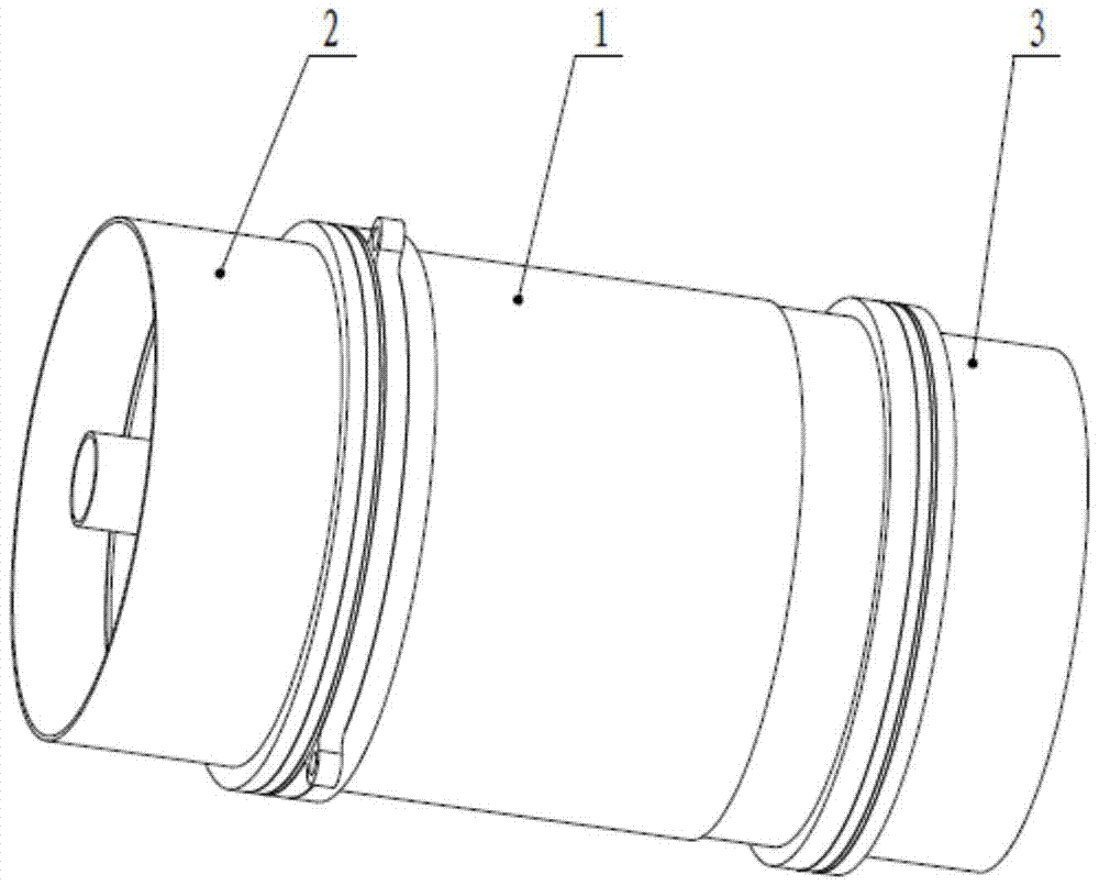
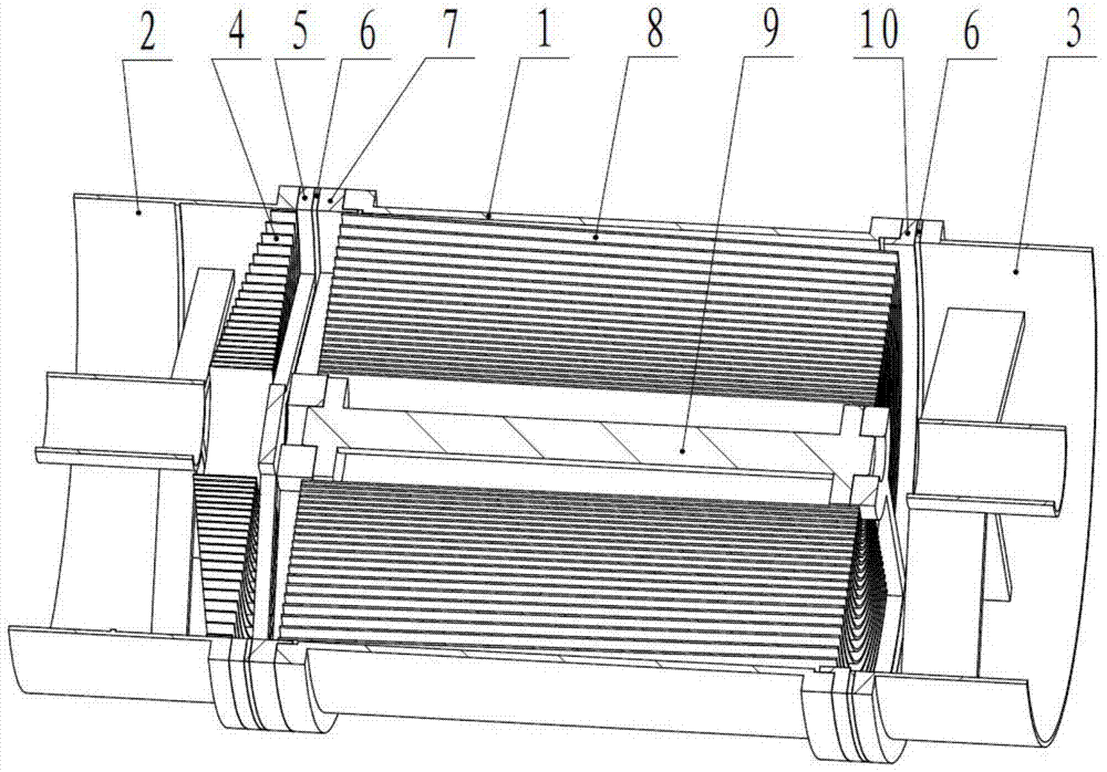
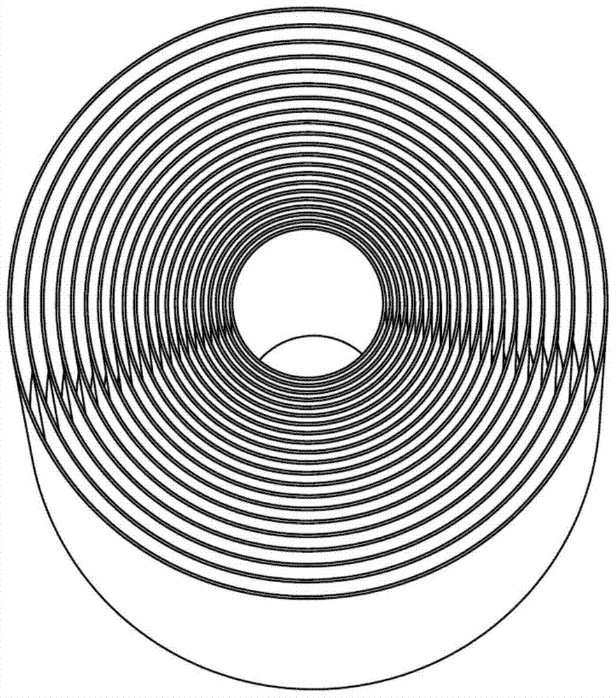
[0042] In this embodiment, in the multi-layer nested conical X-ray grazing incidence optical lens, the cone angle of the truncated cone of the lens in the lens layer 8 is 1° to 3°, and the cone angle gradually decreases from the outer layer to the inner layer. The thickness of the lens ranges from 0.2mm to 0.25mm, and the thickness of the outer layer gradually decreases from the outer layer to the inner layer to maintain basically the same ratio of lens thickness to lens diameter. The length of the lens is 110mm, the field of view is ±7.5arc min, the focal length is 1200mm, and the number of nesting layers is 21. The diameter of the end of the outermost lens near the front spoke plate 7 is 107mm, and the end of the outermost lens near the rear spoke plate 10 The diameter is 102mm, the diameter of the end of the innermost layer lens close to the front spoke plate 7 is 27.2mm, the diameter of the end of the innermost layer lens close to the rear spoke plate 10 is 26mm, the surfac...


PUM


Abstract

The present invention proposes a multi-layer nested conical X-ray grazing incidence optical lens, comprising: a lens barrel (1), a front heat shield assembly (2), a rear heat shield assembly (3), and a front collimation assembly , heat insulation pad (6), front spoke plate (7), lens layer (8), support rod (9), rear spoke plate (10); lens layer (8) is sleeved on the support rod (9), and the lens barrel (1) Set on the outside of the lens layer (8), one end of the lens barrel (1), lens layer (8) and support rod (9) is fixedly connected with the front spoke plate (7), and the other end is connected with the rear spoke plate (10) fixedly connected; the front collimation assembly is installed between the front spoke plate (7) and the front heat shield assembly (2); the rear heat shield assembly (3) is installed on the rear spoke plate (10). The invention uses multi-layer mirrors for reflection to realize large-area collection of soft X-ray photons, and has the advantages of simple structure, large effective area, anti-stray light interference, strong environmental adaptability, simple processing and assembly, and the like.

Description

technical field [0001] The invention belongs to the technical field of space optics and relates to a grazing incidence optical lens. Background technique [0002] X-ray pulsar navigation is suitable for fully autonomous navigation of spacecraft in near-Earth space, deep space exploration, and interstellar flight. It can provide comprehensive navigation information such as position, velocity, attitude, and time for most space mission spacecraft, and realize the navigation of spacecraft. Completely autonomous navigation has the advantages of strong reliability, good stability, high accuracy, and wide applicability. It is a new type of autonomous navigation technology with great development potential. It is an excellent choice for improving the performance of spacecraft autonomous navigation systems. Extremely important engineering practical value and strategic research significance. [0003] The measurement accuracy of X-ray pulse arrival time determines the accuracy of X-ray...

Claims


Application Information

Patent Timeline
Patent Type & Authority Patents(China)
IPC IPC(8): G02B13/00
Inventor 左富昌梅志武邓楼楼李连升莫亚男石永强
Owner BEIJING INST OF CONTROL ENG
Learn More