Ring magnetic core using fe-based nanocrystalline soft magnetic alloy, and magnetic part using same
A soft magnetic alloy, nanocrystal technology, applied in the direction of magnetic core/yoke, magnetic materials, magnetic objects, etc., can solve the problem of difficult to maintain high AC relative permeability, and achieve excellent pulse attenuation characteristics and high magnetic permeability. rate, reduce the effect of excellent performance
- Summary
- Abstract
- Description
- Claims
- Application Information
AI Technical Summary
Problems solved by technology
Method used
Image
Examples
Embodiment 1
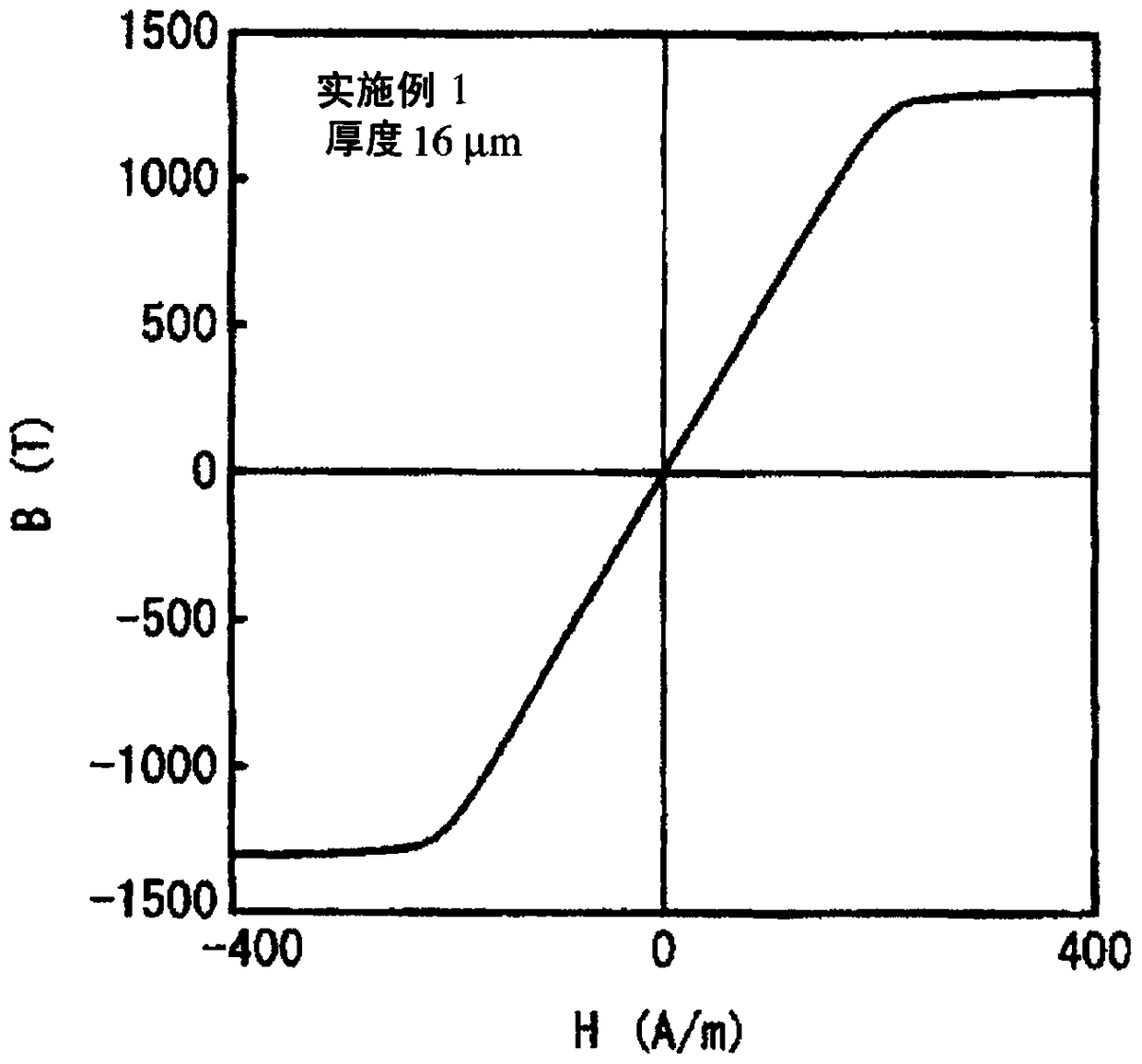
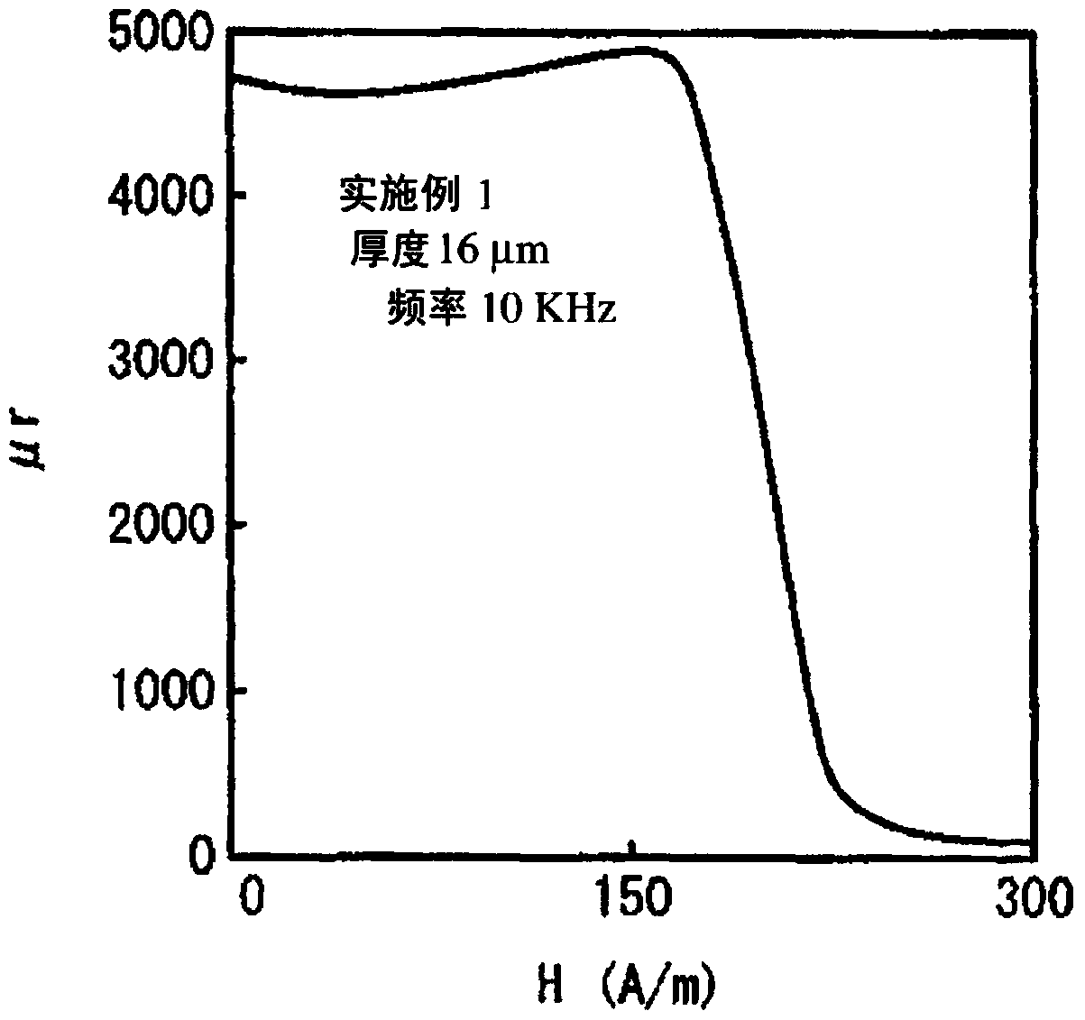
[0081] By single roll method, will have Fe 70.7 Ni 5.0 Cu 0.8 Nb 2.8 Si 10.9 B 9.8 (atomic %) melts were sprayed onto the surface of a high-speed rotating copper roll through nozzles and quenched to obtain alloy strips with thicknesses of 16 μm, 18 μm and 23 μm and widths of 53 mm. It was confirmed by X-ray diffraction measurement that the structures of these alloy ribbons were substantially amorphous. The crystallization temperature Tx of this alloy obtained by differential scanning calorimetry was 490°C.
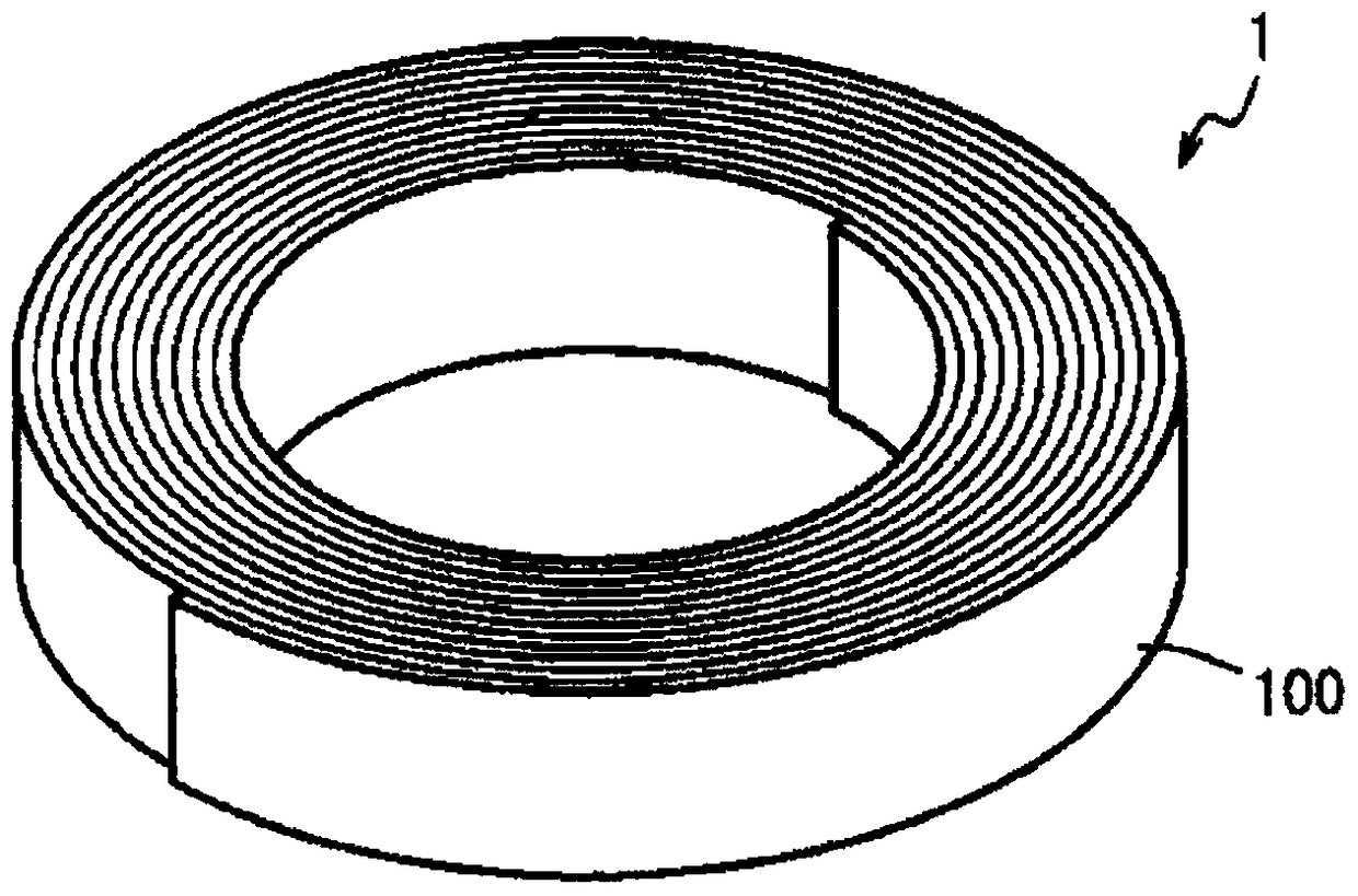
[0082] Each ribbon was cut to obtain two ribbons with a width of 25 mm. Each thin ribbon was wound to obtain an annular tape-wound magnetic core (space factor: 0.9) having an outer diameter of 24.5 mm, an inner diameter of 21 mm, and a height / width of 25 mm. Put the ring-shaped tape-wound magnetic core in the heat treatment furnace controlled by nitrogen atmosphere, and carry out the following heat treatment. The temperature is raised from 420°C to the highest tempe...
Embodiment 2
[0101] Use the thin strip (thickness 18 μm) produced in Example 1 to make a ring-shaped tape-wound magnetic core with an outer diameter of 36.0 mm, an inner diameter of 17.5 mm, and a height / width of 25 mm, put it into a casing, and wind an enameled wire with a wire diameter of 2.5 mm. 17 turns to make a choke coil. The impedance of the choke coil is shown in Figure 5 middle. Depend on Figure 5 It can be seen that the choke coil of Example 2 exhibits excellent impedance performance from a low frequency range to a high frequency range.
[0102] The direct current superposition inductance characteristics of the choke coil of Example 2 and the choke coil of Comparative Example 1 were evaluated. show the result in Figure 6 . Depend on Figure 6 It can be seen that the choke coil of Example 2 is superior to the choke coil of Comparative Example 1 in the direct current superimposed inductance characteristic.
Embodiment 3
[0104]Using the thin ribbon (thickness 18 μm) produced in Example 1 to fabricate an annular tape-wound magnetic core with an outer diameter of 17.8 mm, an inner diameter of 13.8 mm, and a height / width of 25 mm, thereby producing Figure 7 The three-phase common mode choke coil shown. The annular magnetic core is housed in an insulating case 6, and a partition plate 8 for dividing the winding area is provided in the center of the case. The coils 7a, 7b, and 7c of the respective phases are formed by winding an enameled wire with a wire diameter of 2.5 mm three turns. The frequency characteristics of the impedance and inductance of the three-phase common mode choke coil are shown in Figure 8 . In the figure, the solid line represents inductance, and the dotted line represents impedance. Depend on Figure 8 It can be seen that the three-phase common mode choke coil of Example 3 exhibits excellent impedance performance in the low frequency range to the high frequency range.
PUM
| Property | Measurement | Unit |
|---|---|---|
| thickness | aaaaa | aaaaa |
| thickness | aaaaa | aaaaa |
| particle size | aaaaa | aaaaa |
Abstract
Description
Claims
Application Information
 - R&D
- Intellectual Property
- Life Sciences
- Materials
- Tech Scout
- Unparalleled Data Quality
- Higher Quality Content
- 60% Fewer Hallucinations
Browse by: Latest US Patents, China's latest patents, Technical Efficacy Thesaurus, Application Domain, Technology Topic, Popular Technical Reports.
© 2025 PatSnap. All rights reserved.Legal|Privacy policy|Modern Slavery Act Transparency Statement|Sitemap|About US| Contact US: help@patsnap.com


