Magnetic collection feedback type optical fiber current sensor

A fiber-optic current and sensor technology, applied in the field of sensing, can solve the problems that hinder the popularization and application of MOCT, the long-term stability is difficult to be guaranteed, and the magnetic field of the permanent magnet is not stable enough, so as to achieve a large linear measurement range, convenient signal demodulation, and no The effect of easy magnetic saturation

Inactive Publication Date: 2009-05-13
JIANGSU UNIV
View PDF0 Cites 13 Cited by
  • Summary
  • Abstract
  • Description
  • Claims
  • Application Information

AI Technical Summary

Problems solved by technology

However, because the geometric structure of the magneto-optic crystal material, the Verdet constant of the magneto-optic crystal material, and its internal linear birefringence are quite sensitive to changes in the external environment (such as temperature, vibration, etc.) of the conventional optical fiber current sensor, Therefore, in many harsh environments, its long-term stability is difficult to be guaranteed, which also hinders the popularization and application of MOCT in power systems.
From Chen Jinling, Li Hongbin et al. 2006.11 (21) published in the "Power System Automation" magazine ".Comparative Optical Current Transformer Signal Demodulation" and Li Hongbin, Liu Yanbing. 2004.6 (6) published in the "Acta Photonics" According to the paper "Optical Current Transformer Based on Comparative Measurement Method", in 2004 and 2006, Li Hongbin of Huazhong University of Science and Technology proposed to use a comparative method to improve the long-term stability of MOCT. This comparative MOCT must The introduction of a reference magnetic field, usually the magnetic field generated by the permanent magnet, brings a new problem. The magnetic field of the permanent magnet is not stable enough, so it will inevitably affect the final performance of the sensor

Method used


Image

  • Magnetic collection feedback type optical fiber current sensor
  • Magnetic collection feedback type optical fiber current sensor
  • Magnetic collection feedback type optical fiber current sensor

Examples


Embodiment 1

[0027] Follow the steps below to make a magnetic feedback fiber optic current sensor:

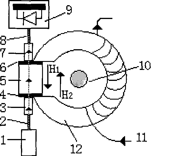
[0028] (1) Glue the optical fiber, self-focusing lens, polarizer, magneto-optical glass and analyzer with glue, specifically: fix the optical fiber 2 on one end of the self-focusing lens 3, and couple the other end of the self-focusing lens 3 to the starting point Polarizer 4; the other side of the polarizer 4 with optical fiber is pasted on one of the sides perpendicular to the axis of the magneto-optical glass 5; the other side is perpendicular to the axis of the magneto-optical glass 5 and an analyzer is bonded The other side of the analyzer 6 is connected with the second self-focusing lens 7; the output optical fiber 8 is fixed on the output end of the second self-focusing lens 7;

[0029] (2) Wind the feedback coil 11 on the magnetic collecting ring 12 with enameled wire

[0030] (3) The magnetic collecting ring 12 around the feedback coil 11 is placed on one side of the magneto-optic...


PUM


Abstract

The invention belongs to the sensing technical field and relates to a magnetic-collection feedback type optical fibre current sensor and a producing method thereof. The magnetic-collection feedback type optical fibre current sensor comprises optical fibre, a self-focusing lens, a polarizer, magneto-optical crystal, analyzer and a magnetic-collection ring, wherein, a feedback coil is arranged on the magnetic-collection ring and is connected with a signal processing circuit. By winding the feedback coil on the magnetic-collection ring, a measuring system of the invention can be ensured to form a closed loop system, thereby the linear measurement range, the linearity, the temperature stability and the dynamic characteristic index of the sensor are improved and the long term stability of the optical fibre current sensor is greatly improved.

Description

technical field [0001] The invention relates to an optical fiber current sensor (OCT), in particular to a manufacturing method of a magneto-optical crystal optical fiber current sensor (MOCT) of a magneto-collecting type. It belongs to the field of sensing technology. technical background [0002] With the development of optical fiber and optical fiber communication technology, the optical fiber current sensor (OCT) has appeared, which brings vitality to the measurement of high voltage and large current. People call them a new generation of products in the field of power measurement. It has the advantages of: anti-electromagnetic interference, good electrical insulation performance, small size, measurement frequency bandwidth and so on. The development of foreign OCTs is relatively early, some OCTs have been connected to the network and have achieved good measurement results; domestic research in this area started late, but the development speed is fast, and some types of O...

Claims


Application Information

Patent Timeline
IPC IPC(8): G01R15/24G01R19/00G02F1/095
Inventor 鲍丙豪张金卫
Owner JIANGSU UNIV
Why Eureka
Try Eureka