Magnetic resonance imaging device

A technology of magnetic resonance imaging and magnets, which is applied in the directions of magnetic resonance measurement, measuring devices, and measuring magnetic variables, etc., and can solve problems such as deterioration of magnetic field uniformity

Inactive Publication Date: 2015-11-18
TOSHIBA MEDICAL SYST CORP
View PDF8 Cites 2 Cited by
  • Summary
  • Abstract
  • Description
  • Claims
  • Application Information

AI Technical Summary

Problems solved by technology

[0004] However, as mentioned above, the gradient magnetic field coil has an iron spacer inside it, so it may move from its original position due to electromagnetic force.
Then, along with this movement, the uniformity of the magnetic field deteriorates

Method used


Image

  • Magnetic resonance imaging device
  • Magnetic resonance imaging device
  • Magnetic resonance imaging device

Examples


no. 1 Embodiment approach

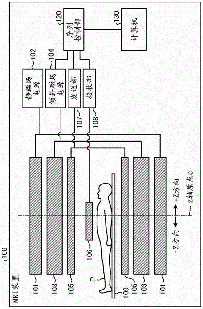
[0026] figure 1 It is a functional block diagram showing the configuration of the MRI apparatus 100 according to the first embodiment. Such as figure 1 As shown, the MRI apparatus 100 includes a static magnetic field magnet 101, a static magnetic field power supply 102, a gradient magnetic field coil 103, a gradient magnetic field power supply 104, a transmitting coil 105, a receiving coil 106, a transmitting unit 107, a receiving unit 108, a bed 109, and a sequence control unit 120. , and computer 130. Hereinafter, the substantially cylindrical structure in which the static field magnet 101 , the gradient coil 103 , and the transmission coil 105 are stacked and supported is referred to as a "coil mechanism" as appropriate. In addition, the subject P (for example, a human body) is not included in the MRI apparatus 100 . in addition, figure 1 The shown structure is just an example. Each part may be suitably combined or configured separately.

[0027] The static field magn...


PUM


Abstract

This magnetic resonance imaging device is provided with a magnetostatic field magnet for generating a magnetostatic field in a space inside a cylinder, and a coil mechanism which is generally cylindrical in shape, disposed within the cylinder of the magnetostatic field magnet, and including a gradient magnetic field coil for generating a gradient magnetic field. Within the coil mechanism, a magnetic body is supported independently of the gradient magnetic field coil, in such a way as to extend along the circumferential direction of the cylindrical shape in proximity to the center of the coil mechanism in the direction of the lengthwise axis.

Description

technical field [0001] Embodiments of the present invention relate to a magnetic resonance imaging apparatus. Background technique [0002] Magnetic resonance imaging is to magnetically excite the nuclear spins of the subject placed in a static magnetic field by RF (Radio Frequency) pulses of Larmor frequency, and the magnetic resonance signals generated along with the excitation The camera method of generating images from the data. [0003] In this magnetic resonance imaging, since the magnetic field is required to be uniform, shimming for correcting the inhomogeneity of the magnetic field is performed. In this shimming there are passive shimming as well as active shimming. Conventionally, passive shimming has been performed by arranging an iron spacer in the layer between the main coil and the shield coil of an active shielded gradient coil (ASGC (Active Shield Gradient Coil)). In addition, in order to reduce the amount of iron shims, a method of arranging iron pieces o...

Claims


Application Information

Patent Timeline
Patent Type & Authority Applications(China)
IPC IPC(8): A61B5/055G01R33/3873
CPCG01R33/3873G01R33/34
Inventor 野上和人坂仓良知田中秀和
Owner TOSHIBA MEDICAL SYST CORP
Why Eureka
Try Eureka