Thermoelectric conversion energy acquisition device based on drop condensation and preparation method

A technology of thermoelectric conversion and energy harvesting, which is applied in the direction of generators, electrical components, generators/motors, etc. that convert kinetic energy into electrical energy, and can solve problems such as original voltage difference, device or system wireless communication interference, and unsatisfactory

Active Publication Date: 2015-11-18
SHANGHAI INST OF MICROSYSTEM & INFORMATION TECH CHINESE ACAD OF SCI
View PDF6 Cites 6 Cited by
  • Summary
  • Abstract
  • Description
  • Claims
  • Application Information

AI Technical Summary

Problems solved by technology

Among them, the piezoelectric energy harvesting device generates electric energy through the piezoelectric effect, which increases the cost due to the need for special piezoelectric materials; the electromagnetic energy harvesting device converts energy such as external vibration into electric energy through an electromagnetic field, and the introduced electromagnetic field may cause Interference with the wireless communication of the device or system; and the electrostatic energy harvesting device requires an external power supply to generate the original voltage difference across the energy conversion capacitor, which cannot meet the requirements of low-power devices in the remote field

Method used


Image

  • Thermoelectric conversion energy acquisition device based on drop condensation and preparation method
  • Thermoelectric conversion energy acquisition device based on drop condensation and preparation method
  • Thermoelectric conversion energy acquisition device based on drop condensation and preparation method

Examples


Embodiment Construction

[0033] Embodiments of the present invention are described below through specific examples, and those skilled in the art can easily understand other advantages and effects of the present invention from the content disclosed in this specification. The present invention can also be implemented or applied through other different specific embodiments, and various modifications or changes can be made to the details in this specification based on different viewpoints and applications without departing from the spirit of the present invention. It should be noted that, in the case of no conflict, the following embodiments and features in the embodiments can be combined with each other.

[0034] It should be noted that the diagrams provided in the following embodiments are only schematically illustrating the basic ideas of the present invention, and only the components related to the present invention are shown in the diagrams rather than the number, shape and shape of the components in ...


PUM


Abstract

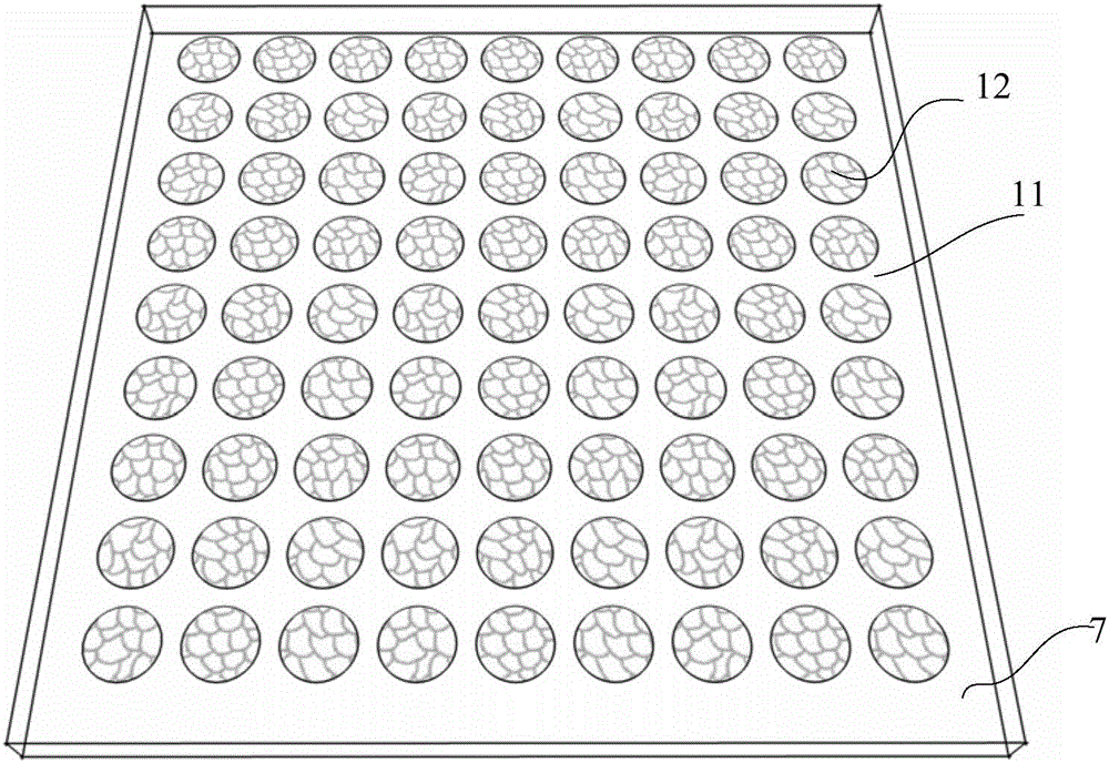
The invention provides a thermoelectric conversion energy acquisition device based on drop condensation and a preparation method. The thermoelectric conversion energy acquisition device comprises a cooling end, an upper polar plate, a lower polar plate, a heat transfer plate and a superhydrophobic wall surface, wherein the heat transfer plate is a metal polar plate with a super strong heat conduction ability, and the lower surface is connected with an outer waste heat source for transferring outer heat energy to liquid water on the upper surface of the heat transfer plate; the side wall and the top layer inner surface of the energy acquisition device adopt superhydrophobic material, water vapors evaporated on the heat transfer plate can be prevented from being condensed on the inner wall, the water vapors are concentrated to be evaporated on the upper polar plate of the top layer inner surface, and dielectric layers of the upper polar plate and the lower polar plate are placed in a vertical opposite mode. When drops condensed on the upper polar plate fall on the surfaces of the dielectric layers, charges on the interface where the drops and the dielectric layers are contacted are redistributed, an instantaneous potential difference between two ends of the inner electrode and the outer electrode is generated, and due to the potential difference, drop collision for power generation is realized, and external heat energy is converted into electric energy.

Description

technical field [0001] The field that the present invention relates to is a thermoelectric conversion energy collection device based on droplet condensation, which belongs to the field of energy collection technology. Background technique [0002] With the development of micro-electro-mechanical systems (MEMS) technology, emerging low-power wireless sensor devices or systems put forward new requirements for micro-power supplies, including portability, wireless remote, separation from redundant power lines, and cost considerations. Portable low-power environmental energy harvesting devices have attracted much attention because they can convert other forms of energy in the environment into electrical energy, and can be used as power sources for microdevices or systems. [0003] The reported energy conversion methods include piezoelectric, electromagnetic, electrostatic and other energy harvesting devices. Among them, the piezoelectric energy harvesting device generates electr...

Claims


Application Information

Patent Timeline
IPC IPC(8): H02N3/00
Inventor 周晓峰刘超然车录锋
Owner SHANGHAI INST OF MICROSYSTEM & INFORMATION TECH CHINESE ACAD OF SCI
Why Eureka
Try Eureka