
A vehicle kinetic energy conversion and recovery device

A kinetic energy conversion and vehicle technology, applied in the direction of power devices, pneumatic power devices, vehicle components, etc., can solve the problems of short service life, large braking energy, large volume and weight of subways, etc., to improve the performance of the whole vehicle, fast and stable Smooth braking and acceleration

Active Publication Date: 2018-03-20
王林翔
View PDF8 Cites 0 Cited by
  • Summary
  • Abstract
  • Description
  • Claims
  • Application Information

AI Technical Summary

Problems solved by technology

Its main disadvantage is the low energy density. Therefore, the same energy requires a larger capacitor bank, and the capacitor has a short service life due to frequent charging and discharging; (3) Flywheel energy storage type, its basic principle and capacitance The principle of the energy storage type is the same, but because the flywheel is in a state of high-speed rotation for a long time and the mass of the flywheel is also large, the problem of frictional energy consumption is serious, and the working life of the flywheel is short
(4) Inverter feedback type, this method is to invert the DC power generated by braking into power frequency AC power and directly feed it back to the power grid, but the technology is complex and the investment in equipment is large, and the related technology is still in the research stage and is not yet mature.
Due to the large volume and weight of the subway, the braking energy is very large, the hydraulic energy storage solution for the bus is not suitable for the recovery of large energy such as the subway

Method used


Image

  • A vehicle kinetic energy conversion and recovery device

Examples


Embodiment Construction

[0021] The present invention will be further described below in conjunction with the accompanying drawings and implementation examples.

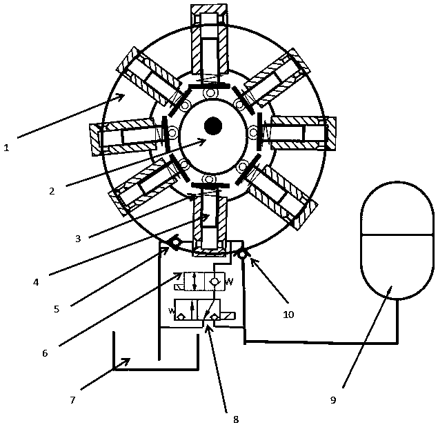
[0022] Such as figure 1 As shown: a plurality of hydraulic plungers 4 are evenly distributed in the pump body 1, and the roller 2 at the end of each plunger rod is pressed against the eccentric wheel 2 under the action of the plunger return spring 3 . Each plunger has a hydraulic circuit to control its oil suction and discharge, charging and discharging. The circuit consists of oil suction check valve 5, oil discharge check valve 10, two-position two-way electromagnetic stop valve 6, and two-position three-way electromagnetic stop valve. 8 composition. figure 1 Only the hydraulic circuit corresponding to one plunger is drawn, and the circuits of other plungers are the same.

[0023] When the vehicle starts to brake, the eccentric wheel is synchronized with the wheel shaft of the vehicle through the switch of the clutch to drive the eccentr...


PUM


Abstract

The invention discloses an automobile kinetic energy conversion and recovery device. The automobile kinetic energy conversion and recovery device is used for storing energy during subway braking and recovering kinetic energy during starting. The automobile kinetic energy conversion and recovery device mainly comprises an eccentric wheel, hydraulic plungers and a corresponding hydraulic loop. During subway braking, the eccentric wheel and an axle rotate synchronously, so that the built-in hydraulic plungers conducts reciprocating radial motion; hydraulic oil is pressed into an energy accumulator through the hydraulic plungers on the basis of the design of the corresponding hydraulic loop, and therefore kinetic energy of the automobile is converted into hydraulic energy to be stored. During subway starting, the device is used as a low-speed large-torque hydraulic motor on the basis of switching control over an electromagnetic valve to push a subway to achieve kinetic energy recovery. According to the automobile kinetic energy conversion and recovery device, the hydraulic mode is utilized for energy storage, braking energy is not converted into electric energy and is just stored as hydraulic energy, and the efficiency is much higher than that of the existing energy storage mode.

Description

technical field [0001] The invention relates to a kinetic energy conversion, storage and recovery device used in the braking and starting process of urban traffic vehicles, more precisely, it relates to a device that converts the kinetic energy of the vehicle into hydraulic energy during the braking process and stores it in the A hydraulic control system that converts hydraulic energy into vehicle kinetic energy during the restart process. Background technique [0002] As an increasingly important means of transportation, urban subways (and other transportation vehicles) will become the mainstream means of transportation in various cities in China in the future. However, the subway is different from the high-speed train. Because of its short station distance, the train starts and brakes frequently. Therefore, from the perspective of energy exchange, the braking energy is considerable. If the braking energy is not considered to be recycled and reused, it will inevitably cause...

Claims


Application Information

Patent Timeline
Patent Type & Authority Patents(China)
IPC IPC(8): B60T1/10B60K6/12
CPCB60K6/12B60T1/10Y02T10/62Y02T10/92
Inventor 王林翔
Owner 王林翔
Learn More