
Generation device for generating DC triboelectricity

A power generation device and triboelectric technology, applied in the direction of friction generators, etc., can solve the problems of complex material selection, poor sealing and portability, and inability to be popularized for rotary friction generators, and achieve simple structure, convenient implementation, and low cost. low effect

Inactive Publication Date: 2015-11-11
JIANGSU UNIV
View PDF6 Cites 22 Cited by
  • Summary
  • Abstract
  • Description
  • Claims
  • Application Information

AI Technical Summary

Problems solved by technology

[0005] The Chinese patent application with the application number 201310507488.2 discloses a rotary direct current friction generator with constant output. Through the friction and sliding between the friction parts, electric charges are generated and the conductive parts are used as commutators to achieve constant direct current output, but the rotation The type DC generator is a planar structure, and a certain rotating space must be reserved for the contact of the contact parts, which reduces the power generation efficiency, and at the same time, the sealing and portability are poor
[0006] The Chinese invention patent application with the application number 201310482286.7 discloses a DC triboelectric generator, which uses three materials with different triboelectric properties to continuously contact and separate, such as polytetrafluoroethylene, polyoxymethylene and aluminum, so as to achieve 2 Different charges are collected on different triboelectric materials to construct a DC friction generator, but the selection of materials for this rotary friction generator has limitations and complexity, the structure is large, and the flow of electrons is realized by the phenomenon of discharge, so it cannot be popularized.

Method used


Image

  • Generation device for generating DC triboelectricity
  • Generation device for generating DC triboelectricity
  • Generation device for generating DC triboelectricity

Examples


Embodiment 1

[0046] The material of the stator friction part is copper; select a flexible polyimide sheet with a thickness of 25-50 μm, ultrasonically clean it for 3-5 minutes, take it out, wash it with a large amount of deionized water and absolute ethanol successively, dry it, and put it Put it into the magnetron sputtering equipment, cover it with a mask, use the copper target with a purity of 99.999% as the sputtering source, and argon as the plasma generation source, first vacuumize the reaction chamber to 5.0×10 -4 Pa, pass in argon gas, adjust the molecular pump plug valve to control the vacuum in the reaction chamber to 1Pa, turn on the AC sputtering source, and the sputtering time is 3~5min, and copper with a thickness of 100~125nm can be obtained on the surface of the polymer; Then the polymer polyimide sheet is pasted on the inner wall of the insulating cylindrical shell 11, wherein the polymer surface serves as the adhesive surface.

[0047] The rotor friction material is made ...

Embodiment 2

[0052] The material of the stator friction part is gold; choose a flexible polyimide sheet with a thickness of 30-50 μm, ultrasonically clean it for 3-5 minutes, take it out, wash it with a large amount of deionized water and absolute ethanol successively, dry it, and put it Put it into the magnetron sputtering equipment, cover it with a mask, use the gold target with a purity of 99.999% as the sputtering source, and argon as the plasma generation source, first vacuumize the reaction chamber to 5.0×10 -4 Pa, feed argon gas, adjust the molecular pump flapper valve to control the vacuum in the reaction chamber to 1Pa, turn on the AC sputtering source, sputter for 2-3min, and obtain gold with a thickness of 50-100nm on the surface of the polymer; then the polymer The polyimide sheet is pasted on the inner wall of the insulating cylindrical shell 11, wherein the polymer surface serves as the adhesive surface.

[0053] The rotor friction material is made of polydimethylsiloxane wit...

Embodiment 3

[0059] The material of the stator friction part is aluminum; choose a flexible polyimide sheet with a thickness of 30-50 μm, ultrasonically clean it for 3-5 minutes, take it out, wash it with a large amount of deionized water and absolute ethanol successively, dry it, and put it Put it into the magnetron sputtering equipment, cover it with a mask, use the aluminum target with a purity of 99.999% as the sputtering source, and argon as the plasma generation source, first vacuumize the reaction chamber to 5.0×10 -4 Pa, pass in argon gas, adjust the molecular pump flapper valve to control the vacuum in the reaction chamber to 1Pa, turn on the AC sputtering source, sputter for 2~3min, and obtain aluminum with a thickness of 75~100nm on the surface of the polymer; then the polymer The polyimide sheet is pasted on the inner wall of the insulating cylindrical shell 11, wherein the polymer surface serves as the adhesive surface.

[0060] The rotor friction material is made of polytetra...


PUM

PropertyMeasurementUnit
Thicknessaaaaaaaaaa
Diameteraaaaaaaaaa
Thicknessaaaaaaaaaa

Abstract

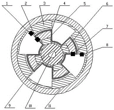
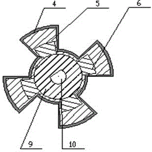
The invention discloses a generation device for generating DC triboelectricity, including a stator, a rotor, an outer casing, a conductive component, a V-shaped support, and a front end cap and a rear end cap. The generation device uses the phenomenon of electrification by friction to generate electricity. A stator friction piece on the inner wall of the outer casing and a rotor friction piece on the outer wall of the rotor are in tight contact and conduct rotational friction therebetween via the rotation of the rotor, and thus generating current. According to the invention, the two friction pieces maintain contact friction therebetween from beginning to end via the uniform circular motion so as to generate inductive charges, and electrons flow through an external circuit and constant direct current is output with the conductive component as a reverse commutator. The generation device is simple in structure and low in cost, and can directly and constantly supply electricity to electronic components without extra rectifying devices, and has excellent social and economic benefits.

Description

technical field [0001] The invention relates to a power generation device, in particular to a direct current friction power generation device. Background technique [0002] Conventional generators in the world rely on electromagnetic induction to generate electricity, using a large amount of ferromagnetic materials and conductive materials such as copper, which are heavy and costly, and even small motors are not easy to carry. Energy harvesting and conversion devices using nanotechnology are likely to play a key role in fabricating and driving self-powered nanodevices and system devices in the future. In 2012, the research group of Professor Wang Zhonglin from the Georgia Institute of Technology in the United States used the triboelectric effect and electrostatic induction principle to convert mechanical energy into electrical energy for the first time. At present, the output power of triboelectric nanomotors is sufficient to drive commercial light-emitting diodes (LEDs), i...

Claims


Application Information

Patent Timeline
IPC IPC(8): H02N1/04
Inventor 程广贵张伟张忠强丁建宁石阳阳郭立强葛道晗凌智勇
Owner JIANGSU UNIV
Learn More