
Boiler denitration control method based on outlet NOx content control and system thereof

A control method and control system technology, applied in the field of boiler denitrification control and system based on outlet NOx content control, can solve problems such as increased operating costs, damage to downstream main equipment, and excessive denitrification, so as to improve the system's anti-disturbance ability, Effect of controlling denitrification operation cost, preventing corrosion and clogging

Inactive Publication Date: 2015-11-11
DATANG HUAYIN ELECTRIC POWER
View PDF4 Cites 43 Cited by
  • Summary
  • Abstract
  • Description
  • Claims
  • Application Information

AI Technical Summary

Problems solved by technology

This control method is based on the denitration efficiency and catalyst denitrification ability. Under this control method, the system removes NO from the flue gas according to a fixed ammonia nitrogen molar ratio. x , this control method is a single-loop control system with adjustable set value. The control loop is simple and easy to debug and adjust. Its disadvantage is that it will cause excessive denitrification and increase operating costs. The specific performance is:
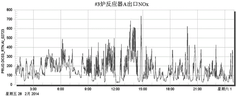
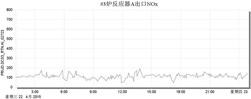
[0004] 1. After the denitrification and ammonia injection are automatically put in, the controlled SCR (Selective Catalytic Reduction, that is, selective catalytic reduction technology) exports NO x The concentration adjustment quality is very poor, especially in the process of changing the load, the outlet NOX fluctuates too much, exceeding the NO allowed by the environmental assessment x Emission value standard
[0005] 2. Excessive denitrification occurs, resulting in a high ammonia escape rate at the SCR outlet, causing damage to downstream main equipment, and at the same time consumes a lot of ammonia, increasing operating costs

Method used


Image

  • Boiler denitration control method based on outlet NOx content control and system thereof
  • Boiler denitration control method based on outlet NOx content control and system thereof
  • Boiler denitration control method based on outlet NOx content control and system thereof

Examples


Embodiment 1

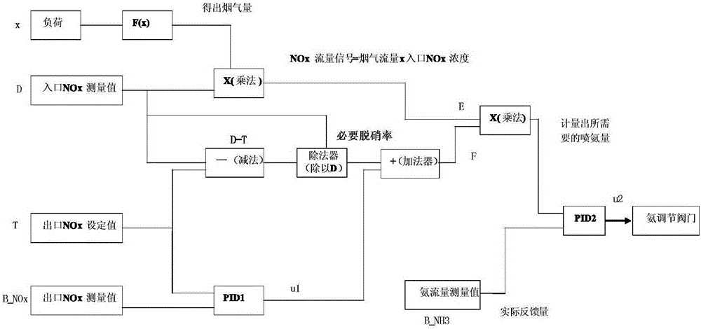
[0045] Such as figure 1 , in the boiler denitrification control process, the following calculation and control processes are involved:

[0046] 1. Calculate the flue gas flow rate of the boiler. The flue gas flow rate of the new ammonia injection automatic logic is based on the empirical value of the corresponding relationship between load and flue gas volume, and through the segmented function FX [this function is obtained based on long-term operation experience in the production process. A more general general formula, applicable to most cases], for inlet flue gas NO x The concentration is corrected, and the ultimate goal is to obtain a more accurate demand for ammonia supply.

[0047] If the boiler is multi-coal mixed combustion, when the coal quality changes, the corresponding relationship between the load and the flue gas volume will also change, and the parameters of FX can be adjusted appropriately according to the actual situation to meet the needs of automatic adjustme...


PUM


Abstract

The invention discloses a boiler denitration control method based on outlet NOx content control and a system thereof. Two PID controllers are used to adjust an ammonia spraying amount so as to finally control a NOx content of a boiler outlet. During a control process, an inlet flue gas NOx flow E needs to be determined in real time and the E satisfies the following equation: E=DFGA*D, wherein the D is the NOx content (concentration) of the boiler inlet; the DFGA is an inlet flue gas amount; and the DFGA satisfies the following equation: DFGA=x*F(x). An output signal of a second PID controller is u2. The u2 expresses an opening degree of an ammonia spraying regulating valve. The opening degree of the ammonia spraying regulating valve is adjusted according to the u2 and the boiler denitration control is realized. The boiler denitration control method based on the outlet NOx content control and the system are easy to perform. Liquid ammonia consumption and a chimney NOx concentration can be greatly reduced.

Description

technical field [0001] The invention relates to a method based on export NO x A content-controlled boiler denitrification control method and system. Background technique [0002] Existing large-scale thermal power units (such as "W" type flame boiler supercritical units), the boiler combustion is difficult to control, and because of the mixed combustion of multiple coals, the inlet NO x Concentrations often exceed 1300mg / Nm 3 , so that the original denitrification and ammonia injection automatic system based on the fixed molar ratio control method cannot meet the needs of operation. [0003] In the existing control method, the automatic control of denitrification and ammonia injection is based on the inlet NO x Concentration and flue gas volume, calculation of denitrification ammonia gas flow, can be called a fixed molar ratio control method. This control method is based on the denitration efficiency and catalyst denitrification ability. Under this control method, the sy...

Claims


Application Information

Patent Timeline
IPC IPC(8): G05B11/42B01D53/86B01D53/56
Inventor 赵国光段卫民
Owner DATANG HUAYIN ELECTRIC POWER
Learn More