Motor control device
A technology for control devices and electric motors, which is applied in the fields of motor control, motor generator control, AC motor control, etc., and can solve problems such as difficulty in detecting or estimating induced voltage, deterioration of detection accuracy and speed estimation accuracy, etc.
- Summary
- Abstract
- Description
- Claims
- Application Information
AI Technical Summary
Problems solved by technology
Method used
Image

Examples
Embodiment approach 1
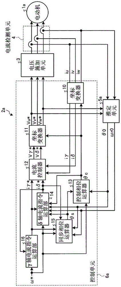
[0028] figure 1 It is a block diagram showing the configuration of the motor control device according to Embodiment 1 of the present invention. In Embodiment 1, the case where switching from synchronous current control to sensorless vector control via switching control, or switching from sensorless vector control to synchronous current control via switching control will be described. Case.
[0029] In addition, the so-called sensorless vector control refers to a method of estimating the rotation speed of the motor from the induced voltage of the motor without installing a position sensor in the motor, or even if a position sensor is installed in the motor without using the position sensor, and controlling the motor speed. The speed is controlled so that the estimated speed matches the speed command. In addition, the so-called synchronous current control refers to a method of controlling the motor speed so that the motor speed is controlled by providing an arbitrarily set syn...
Embodiment approach 2
[0066] Figure 5 It is a block diagram showing the configuration of a motor control device according to Embodiment 2 of the present invention. In addition, in Figure 5 in, right with figure 1 The same or equivalent structural elements shown in (Embodiment 1) are denoted by the same reference numerals. Here, the description will focus on the part related to the second embodiment.
[0067] In Embodiment 2, a case will be described in which the overall drive control is sensorless vector control, phase estimation error correction by a high-frequency superposition method is performed in the low-speed range, and phase estimation error correction is performed in the medium-to-high-speed range. In this method, the phase estimation error correction by the high-frequency superposition method is not performed, but the maximum efficiency control and the maximum torque control by only the sensorless vector control are performed. Here, the so-called sensorless vector control, which has...
PUM
 Abstract
Description
Claims
Application Information
 - R&D
- Intellectual Property
- Life Sciences
- Materials
- Tech Scout
- Unparalleled Data Quality
- Higher Quality Content
- 60% Fewer Hallucinations
Browse by: Latest US Patents, China's latest patents, Technical Efficacy Thesaurus, Application Domain, Technology Topic, Popular Technical Reports.
© 2025 PatSnap. All rights reserved.Legal|Privacy policy|Modern Slavery Act Transparency Statement|Sitemap|About US| Contact US: help@patsnap.com