
Device for generating millimeter wave signals by using broadband light source

A broadband light source and millimeter wave technology, applied in the field of optical fiber communication and optical fiber sensing, can solve the problems such as the instability of the phase difference between optical signals cannot be guaranteed, the modulation mode of the microwave signal is fixed, the parameters of the microwave signal are limited, etc., and the phase relationship can be achieved. The effect of stability, low phase noise and simple structure

Inactive Publication Date: 2015-10-14
XIDIAN UNIV
View PDF5 Cites 0 Cited by
  • Summary
  • Abstract
  • Description
  • Claims
  • Application Information

AI Technical Summary

Problems solved by technology

[0003] At present, the mainstream optical microwave signal generation technology can be mainly divided into three categories: (1) optical heterodyne method, since two or more light sources are required for input, the stability of the phase difference between the optical signals cannot be guaranteed, which also leads to The generated microwave signal is affected by phase noise
(2) Frequency-time domain mapping method. The modulation method of microwave signals generated by this method is generally fixed to intensity modulation. It is difficult to directly realize high-order modulation formats by this method. Combined with spectral construction technology, the parameters of the generated microwave signal are often limited by the design of the spectral construction module
(3) The external modulation method is generally implemented by adding an intensity modulator at the sending end. It is the simplest and most effective method. It has high reliability and low cost, but it requires a high-quality reference signal source

Method used


Image

  • Device for generating millimeter wave signals by using broadband light source

Examples


specific Embodiment 1

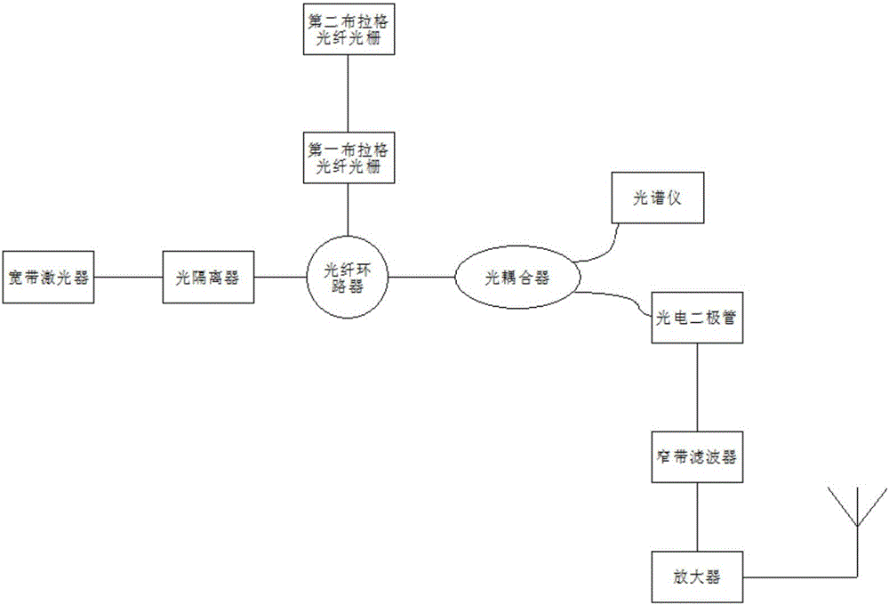
[0028] like figure 1 As shown, a device for generating a millimeter wave signal using a broadband light source, including

[0029] a broadband laser for outputting optical signals of multiple wavelengths;

[0030] An optical isolator, connected to the broadband laser, is used to isolate reflected light to prevent interference with the broadband laser;

[0031] A fiber optic circulator, connected to the optical isolator, is used to transmit optical signals to the first Fiber Bragg Grating and the second Fiber Bragg Grating and receive reflected optical signals of the first Fiber Bragg Grating and the second Fiber Bragg Grating;

[0032] The first fiber Bragg grating is connected with the optical fiber circulator, and is used for selectively outputting the optical signal input by the optical fiber circulator and narrowing the output optical signal;

[0033] The second fiber Bragg grating is connected to the first fiber Bragg grating, and is used for selectively outputting the ...

specific Embodiment 2

[0047] It is roughly the same as the specific embodiment 1, and the only difference is that the wavelengths of the optical signals selected by the first fiber Bragg grating and the second fiber Bragg grating are different.

[0048] If the wavelength of the optical signal selected by the first fiber Bragg grating is λ 1 =1549.64nm, the wavelength of the optical signal selected by the second fiber Bragg grating is λ 2 =1550.36nm, the generated millimeter wave signal Δλ=0.72nm (ie Δv=90GHz);

[0049]If the wavelength of the optical signal selected by the first fiber Bragg grating is λ 1 =1550nm, the wavelength of the optical signal selected by the second fiber Bragg grating is λ 2 =1551nm, the generated millimeter wave signal Δλ=1nm (ie Δv=125GHz);

specific Embodiment 3

[0050] It is roughly the same as that of the specific embodiment 1, and the only difference is that the wavelengths of the optical signals selected by the first fiber Bragg grating and the second fiber Bragg grating are different.

[0051] If the wavelength of the optical signal selected by the first fiber Bragg grating is λ 1 =1549.04nm, the wavelength of the optical signal selected by the second fiber Bragg grating is λ 2 =1550.96nm, the generated millimeter wave signal Δλ=1.92nm (ie Δv=240GHz);

[0052] If the wavelength of the optical signal selected by the first fiber Bragg grating is λ 1 =1548.8nm, the wavelength of the optical signal selected by the second fiber Bragg grating is λ 2 =1551.2nm, the generated millimeter wave signal Δλ=2.4nm (ie Δv≈300GHz)


PUM


Abstract

The invention relates to a device for generating millimeter wave signals by using a broadband light source. An optical isolator is connected with a broadband laser; an optical fiber loop device is connected with the optical isolator; a first Bragg fiber grating is connected with the optical fiber loop device; a second Bragg fiber grating is connected with the first Bragg fiber grating; an optical coupler is connected with the optical fiber loop device; a spectrograph is connected with the optical coupler; a photoelectric diode is connected with the optical coupler; a narrowband filter is connected with the photoelectric diode; an amplifier is connected with the narrowband filter; and an antenna is connected with the amplifier. According to the device of the invention, the broadband laser can output optical signals of a plurality of wavelengths, so that wide-range millimeter wave signals can be obtained; after the optical signals are pressed and narrowed, so that the bandwidth of obtained optical signals is large, and the phase relationship of the optical signals is stable, and the frequency stability of the optical signals is high, and the phase noise of the optical signals is low; and the device of the invention is of structural simplicity.

Description

technical field [0001] The invention belongs to the field of optical fiber communication and optical fiber sensing, in particular to a device for generating millimeter wave signals by a broadband light source. Background technique [0002] The use of photons to generate millimeter wave signals has a very wide range of applications in the fields of radar, optical fiber communication, optical sensing and radio frequency optical fiber transmission. method to generate millimeter wave signals. The signal generated by this method has low transmission loss in the optical fiber line, and the signal can be transmitted long-distance through the amplifier. [0003] At present, the mainstream optical microwave signal generation technology can be mainly divided into three categories: (1) optical heterodyne method, since two or more light sources are required for input, the stability of the phase difference between the optical signals cannot be guaranteed, which also leads to The genera...

Claims


Application Information

Patent Timeline
Patent Type & Authority Applications(China)
IPC IPC(8): H01S3/067H01S3/16G02B6/293
Inventor 曹长庆曾晓冬王香冯喆珺霍熠伟罗龙陈渲麒
Owner XIDIAN UNIV
Learn More