High Gain Low Profile Circularly Polarized Antenna

A circularly polarized antenna, low profile technology, applied in the field of communication antennas, can solve the problems of less circularly polarized antennas, the antenna gain is not stable enough, the antenna gain decays quickly, etc., and achieves light weight, compact structure, and stable gain. Effects of Features

Active Publication Date: 2022-04-01
北京星英联微波科技有限责任公司
View PDF8 Cites 0 Cited by
  • Summary
  • Abstract
  • Description
  • Claims
  • Application Information

AI Technical Summary

Problems solved by technology

However, in the existing technology, low-profile microstrip antennas based on high-impedance surfaces often only have good gain characteristics at the center frequency, and the gain of the antenna decays quickly when the center frequency is deviated from the center frequency.
In other words, the gain of this type of antenna is not stable enough in the working frequency band and is greatly affected by frequency
In addition, low-profile microstrip antennas based on high-impedance surfaces reported in the prior art are often in the form of a single linear polarization, and there are fewer reports on circularly polarized antennas

Method used


Image

  • High Gain Low Profile Circularly Polarized Antenna
  • High Gain Low Profile Circularly Polarized Antenna
  • High Gain Low Profile Circularly Polarized Antenna

Examples


Embodiment Construction

[0030] The technical solutions in the embodiments of the present invention are clearly and completely described below in conjunction with the accompanying drawings in the embodiments of the present invention. Obviously, the described embodiments are only part of the embodiments of the present invention, not all of them. Based on the embodiments of the present invention, all other embodiments obtained by persons of ordinary skill in the art without making creative efforts belong to the protection scope of the present invention.

[0031] In the following description, a lot of specific details are set forth in order to fully understand the present invention, but the present invention can also be implemented in other ways different from those described here, and those skilled in the art can do it without departing from the meaning of the present invention. By analogy, the present invention is therefore not limited to the specific examples disclosed below.

[0032] Such as figure ...


PUM


Abstract

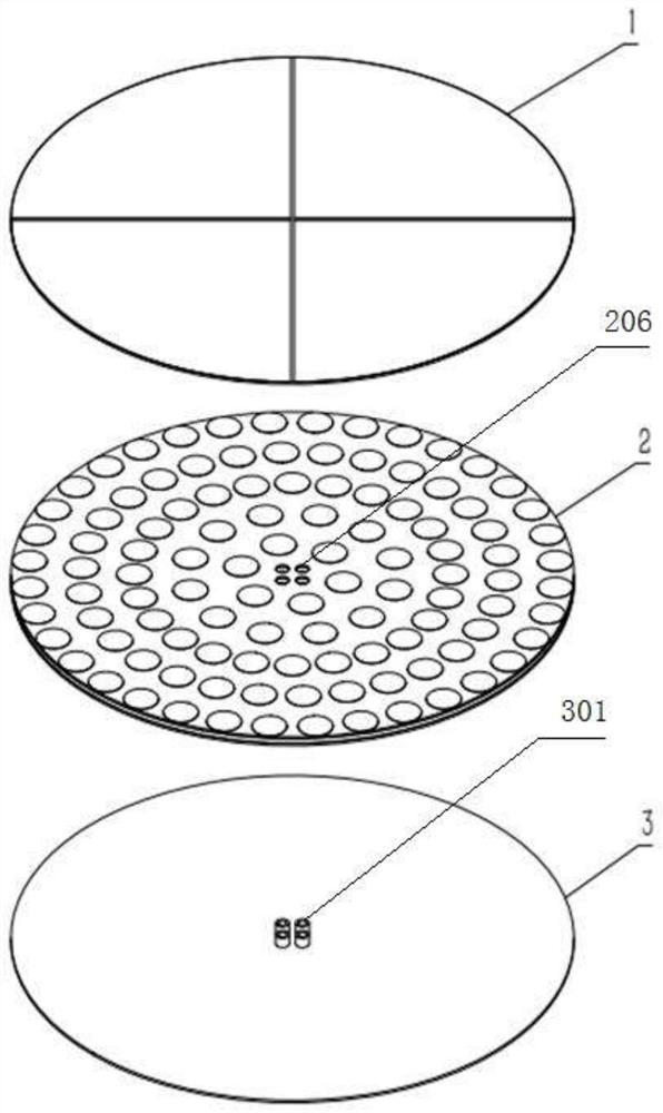
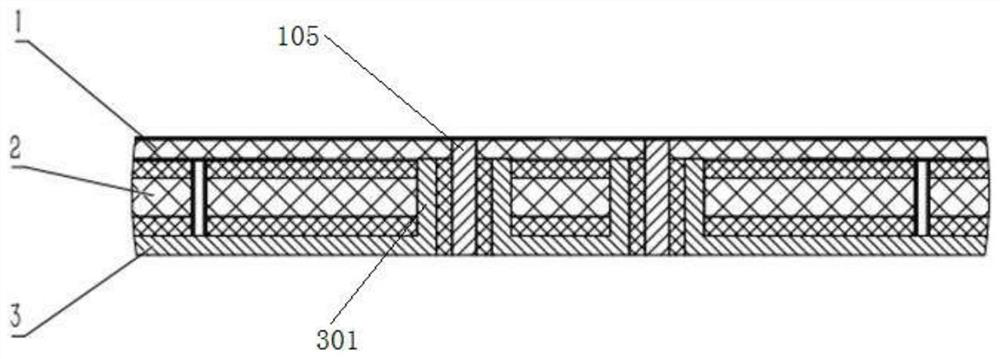
The invention discloses a circularly polarized antenna with high gain and low profile, and relates to the technical field of communication antennas. The antenna includes a circularly polarized patch at the top, a composite dielectric high-impedance surface array at the middle, and a metal backplane at the bottom. The circularly polarized patch includes a patch medium layer, and the upper surface of the patch medium layer is formed with a first sector patch, a second sector patch, a third sector patch and a fourth sector patch, and the patch Four feeding coaxial cables are arranged near the center of the dielectric layer, and the feeding coaxial cables are vertically arranged, and the upper end of each feeding coaxial cable is respectively electrically connected to a corresponding fan-shaped patch. The other end of the feeding coaxial line extends through the patch medium layer to the outside of the lower surface of the patch medium layer. In the working frequency band, the phase of the composite dielectric high-impedance surface array in the middle layer of the antenna is slightly affected by the frequency, which ensures stable gain characteristics of the antenna.

Description

technical field [0001] The invention relates to the technical field of communication antennas, in particular to a circularly polarized antenna with high gain and low profile. Background technique [0002] As a front-end component for effectively transmitting and receiving electromagnetic waves in a wireless communication system, the antenna is mainly used to complete the mutual conversion between electromagnetic waves and guided waves, and its performance will directly affect the communication effect of the entire system. There are many types of antennas. For communication systems with different functions and application environments, the antenna needs to choose a suitable structure and radiation performance that meets the technical requirements of the system. [0003] Whether in civilian or military applications, people have higher and higher requirements for the mobility, flexibility and integration of communication systems. Low-profile antennas are more popular in the ap...

Claims


Application Information

Patent Timeline
Patent Type & Authority Patents(China)
IPC IPC(8): H01Q1/36H01Q1/50
CPCH01Q1/36H01Q1/50
Inventor 胡南
Owner 北京星英联微波科技有限责任公司
Why Eureka
Try Eureka