


Quick Research
Generate reliable direction feasibility study reports for your R&D in just a few steps.

Technical Q&A
Discover and master advanced knowledge NOW. Basics, ideas, possibilities, all at once.

Find Solutions
As an expert in R&D theories, this can generate solutions to your technical problems instantly.

Evaluate Feasibility
Analyze your overall solution with one click, know your potential R&D risks in advance.

Monitor Landscape
Get weekly tech updates, stay abreast of the latest tech innovations and key insights.
Method for carrying out power outputting and gas conveying through low-temperature liquid
A low-temperature liquid and power output technology, which is applied in the field of gas transportation and low-temperature liquid power output, can solve problems such as large energy consumption, and achieve the effect of reducing energy consumption and saving energy.
- Summary
- Abstract
- Description
- Claims
- Application Information
AI Technical Summary
Problems solved by technology
Method used
Image

Examples
Embodiment 1
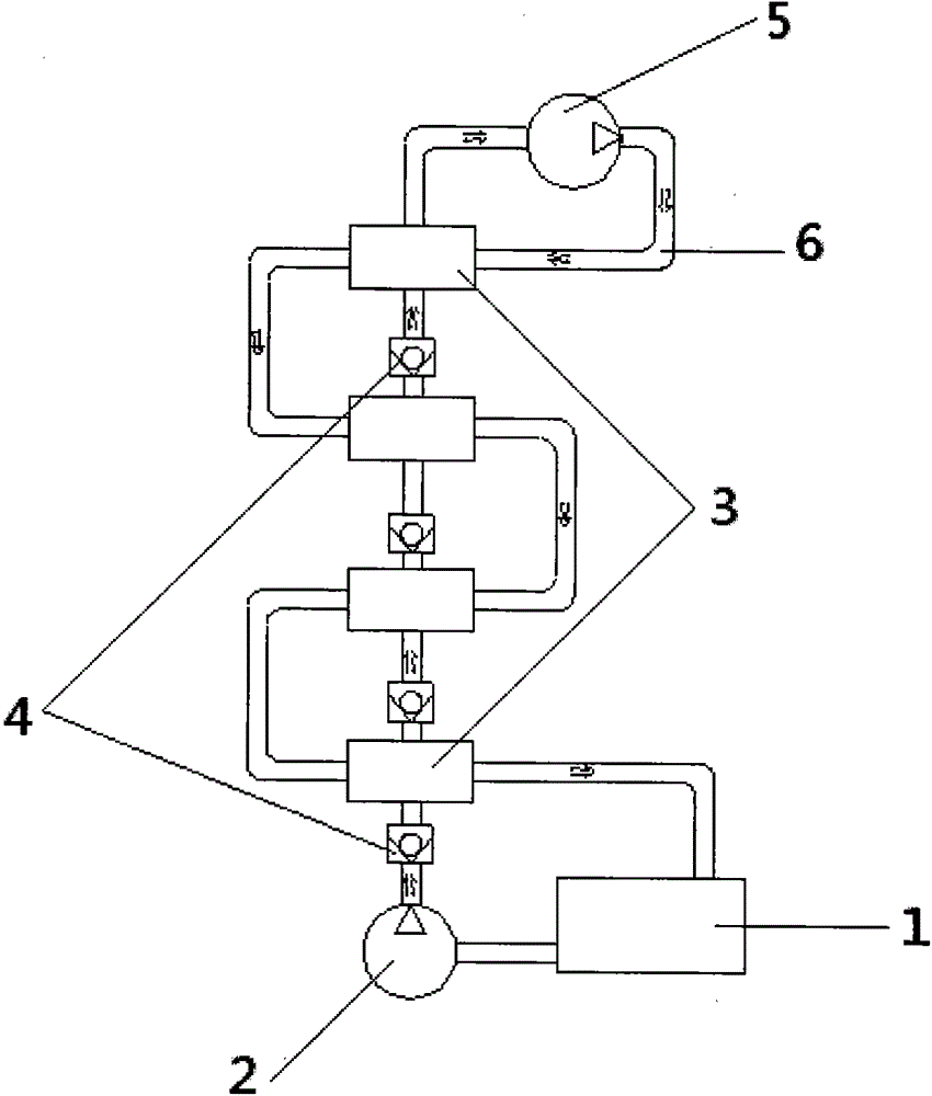
[0024] Embodiment 1: power output
[0025] Such as figure 1 As shown, the low temperature heat preservation liquid storage tank 1 is filled with low temperature liquid, and the outlet of the low temperature heat preservation liquid storage tank is connected to the hydraulic pump 2 . The output port of the hydraulic pump is connected to the first-stage cooling and evaporating heat exchanger 3 through a one-way valve 4. The heat exchanger unit is called the final refrigeration evaporative heat exchanger. A one-way valve 4 is provided between the two-stage refrigeration evaporative heat exchanger units, and a check valve is connected to the inlet end of the first-stage refrigeration evaporative heat exchanger unit; The outlet is connected to the inlet of the pneumatic motor 5, and the outlet of the pneumatic motor 5 is connected to the circulation return pipe 6, and the circulation return pipe is connected to the low-temperature heat preservation liquid storage tank 1 through t...
Embodiment 2
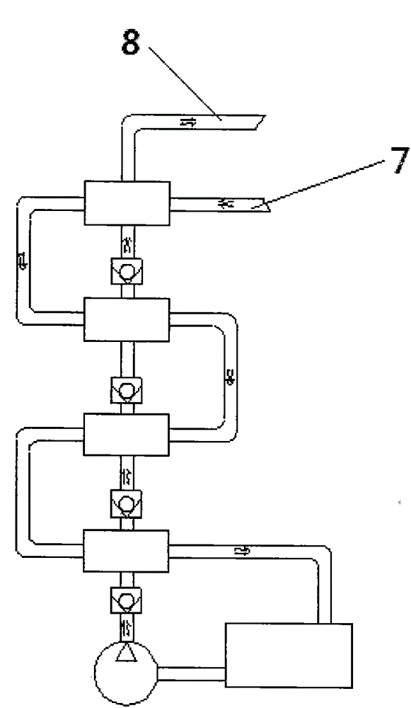
[0028] Example 2: Gas delivery
[0029] Such as figure 2 As shown, the structural difference between Embodiment 2 and Embodiment 1 is that the low-pressure gas input pipe 7 is connected to the final refrigeration evaporative heat exchanger unit, and the outlet of the final refrigeration evaporative heat exchanger unit is connected to the high-pressure gas output pipe 8 . The low-pressure gas passes through the last-stage refrigeration evaporative heat exchanger unit and begins to cool down step by step, until the outflow of the first-stage refrigeration evaporative heat exchanger unit has become a low-temperature liquid and enters the low-temperature insulation storage tank, and then passes through the hydraulic pump to transfer the low-temperature liquid from the The low-temperature heat preservation liquid storage tank is pumped out and pressed into the first-stage refrigeration evaporative heat exchanger unit, and the fourth-stage (last stage) refrigeration evaporative hea...
PUM
 Abstract
Description
Claims
Application Information
 - R&D Engineer
- R&D Manager
- IP Professional
- Industry Leading Data Capabilities
- Powerful AI technology
- Patent DNA Extraction
Browse by: Latest US Patents, China's latest patents, Technical Efficacy Thesaurus, Application Domain, Technology Topic, Popular Technical Reports.
© 2024 PatSnap. All rights reserved.Legal|Privacy policy|Modern Slavery Act Transparency Statement|Sitemap|About US| Contact US: help@patsnap.com