Multi-cylinder rotary compressor
A rotary compressor and compression mechanism technology, applied in the field of compressors, can solve problems such as wear failure, increased vibration, and increased length between shafts, and achieve the effects of reducing assembly errors, improving rigidity, and expanding eccentricity.
- Summary
- Abstract
- Description
- Claims
- Application Information
AI Technical Summary
Problems solved by technology
Method used
Image

Examples
Embodiment 1
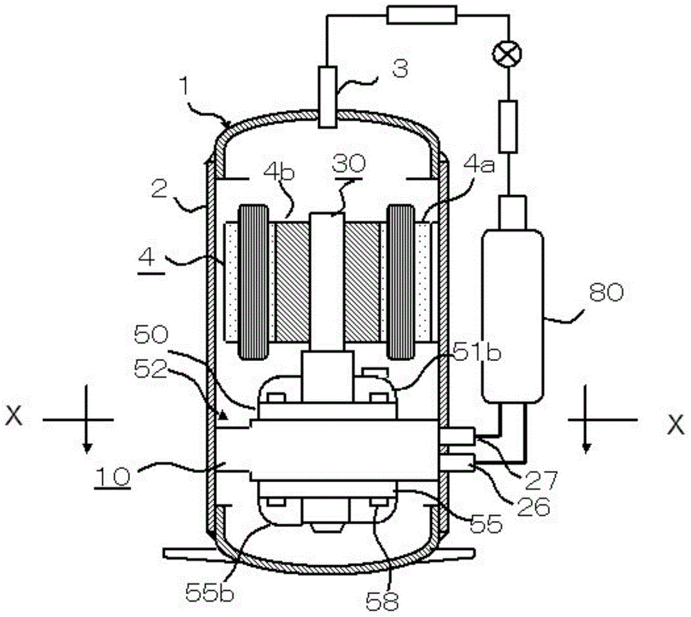
[0067] figure 1 In the illustrated multi-cylinder rotary compressor 1 , the outer circumference of a stator 4 a constituting a motor 4 and the outer circumference of a cylinder 10 included in a compression mechanism unit 52 of the rotary compressor are fixed to the inner diameter of a cylindrical housing 2 . The compression mechanism unit 52 is composed of the first cylinder 10 in which the two compression chambers and the intermediate partition are integrated, the main bearing 50 and the sub-bearing 55 connected to these compression chambers, the crankshaft 30 sliding on these bearings, and the like. The rotor 4b is fixed in the crankshaft 30 .
[0068] The exhaust pipe 3 connected to the upper end of the housing 2 , the first air intake pipe 26 connected to the outer periphery of the first cylinder 10 , and the second air intake pipe 27 are connected to the accumulator 80 . The exhaust pipe 3 and the accumulator 80 are respectively connected to the high pressure side and th...
Embodiment 2
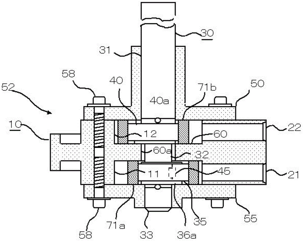
[0085] Figure 7 It is the intermediate bearing 60b which slides the intermediate|middle plate hole 60a and the intermediate shaft 32 of Example 1. Here, the intermediate partition plate hole 60a in a state of sliding engagement with the intermediate shaft 32 is referred to as an intermediate bearing 60b. As a result, three bearings including the main bearing 50 , the intermediate bearing 60 b and the sub bearing 55 are slidingly fitted to the crankshaft 30 .
[0086] The intermediate bearing 60b is the third bearing, the piston 71b that rotates at a phase angle of 180 degrees, and the repetitive load generated by the compression force and the centrifugal force of the piston 71a, and is supported by the intermediate bearing 60b, the main bearing 50, the intermediate bearing 60b, and the sub bearing 55 .
[0087] In Example 2, by adding an intermediate bearing 60b for slidingly supporting the intermediate shaft 32, the runout of the sliding parts interlocking with the cranksh...
Embodiment 3
[0091] Figure 9 The design is: in Figure 7 A single intermediate plate 62 provided with an intermediate plate muffler 62 a and a second cylinder 130 provided with a compression chamber 13 are added as a three-cylinder compression mechanism section 53 in the middle of the two-cylinder compression mechanism section 52 . In this design, the two intermediate shafts, the intermediate partition plate, and the intermediate plate are slidingly fitted, so they become four bearings. The auxiliary shaft 33, the intermediate shaft 32a, and the intermediate shaft 32b have the same diameter, and the first eccentric shaft 35 and the third eccentric shaft 43 are separately assembled.
[0092] The additional single second cylinder 130 and the intermediate plate 62 are connected by screws to the highly rigid first cylinder 10, so the reliability and performance of the three-cylinder compression mechanism 53 are reduced, and high quality is maintained. In addition, the intermediate muffler 6...
PUM
 Abstract
Description
Claims
Application Information
 - R&D
- Intellectual Property
- Life Sciences
- Materials
- Tech Scout
- Unparalleled Data Quality
- Higher Quality Content
- 60% Fewer Hallucinations
Browse by: Latest US Patents, China's latest patents, Technical Efficacy Thesaurus, Application Domain, Technology Topic, Popular Technical Reports.
© 2025 PatSnap. All rights reserved.Legal|Privacy policy|Modern Slavery Act Transparency Statement|Sitemap|About US| Contact US: help@patsnap.com