A kind of construction method of cage type space grid structure steel bar connector with cone

一种钢筋连接器、空间网格的技术,应用在结构要素、建筑构件、制造工具等方向,能够解决强度降低、连接强度降低、施工难度增大等问题,达到抗弯能力提高、自身重量减轻、节约建筑成本的效果

Active Publication Date: 2017-05-10
SHANDONG ONE STAR CO NSTRUCTION TECH CO LTD
View PDF5 Cites 0 Cited by
  • Summary
  • Abstract
  • Description
  • Claims
  • Application Information

AI Technical Summary

Problems solved by technology

But when the tube wall is thicker, the diameter of the sleeve must be larger, and the grouting sleeve with a larger diameter cannot meet the national regulations in use. Concrete thickness requirements, this thickness is collectively referred to as the protective layer, the protective layer for slabs and walls is required to be at least 15 mm, and the protective layer thickness for building beams or columns is at least 20 mm. The shortage of this grouting sleeve is: due to the The space is limited. When the position of the longitudinal reinforcement remains unchanged, the thickness of the protective layer between the outside of the grouting sleeve and the upper stirrup of the building component cannot meet the requirements of the national standard. Therefore, the longitudinal reinforcement in the concrete of the prefabricated component must be moved to the center of the interior. In order to increase the thickness of the protective layer between the steel bar connector and the building component stirrup, however, this will cause the longitudinal steel bar to be far away from the outer wall of the prefabricated part, resulting in a smaller ability to resist the bending moment of the wall, thus Reduce the mechanical performance of prefabricated components; at the same time, when the protective layer in the prefabricated component reaches the thicker requirement, it will cause the longitudinal reinforcement to move to the middle, affecting the ability of the prefabricated component to resist bending moments; when the prefabricated structural reinforcement moves inward , the ability to resist the bending moment becomes smaller. Therefore, the longitudinal reinforcement of the prefabricated component should be evenly distributed on both sides of the component and cannot move concentratedly in the middle. This requires the diameter of the grouting sleeve to be reduced to meet the requirements of the connection The distance of the longitudinal reinforcement moving to the middle of the prefabricated wall is as small as possible
However, the smaller the hole diameter of the grouting sleeve, the lower the grouting amount, resulting in reduced connection strength, and according to the national standard, the first horizontally distributed reinforcement of the shear wall is 50 mm from the bottom of the wall, but the height of the grouting sleeve is generally If it is greater than 100 mm, at least one horizontal stirrup must be provided outside the grouting sleeve located at the edge of the wall or at the connection part of the shear wall. The outer wall of the component is narrow, which cannot meet the requirements of the thickness of the concrete protective layer. Sometimes the steel bars are exposed, which leads to the corrosion of the steel bars, and the joint force of the steel bars and the concrete cannot be exerted, which seriously affects the building quality; in addition, the existing grouting sleeve is in use. , in order to meet the requirements of the national standard, it is necessary to add anti-cracking steel bars in the wall to prevent cracks in the concrete members after being stressed, resulting in increased construction costs and increased construction difficulty; the ring-shaped trapezoidal protrusions on the inner wall of the grouting sleeve are prone to fracture , leading to a substantial reduction in its strength

Method used


Image

  • A kind of construction method of cage type space grid structure steel bar connector with cone
  • A kind of construction method of cage type space grid structure steel bar connector with cone
  • A kind of construction method of cage type space grid structure steel bar connector with cone

Examples


Embodiment Construction

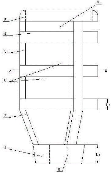
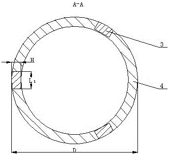
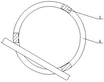
[0013] A steel bar connector with a cage space grid structure with a cone according to the present invention includes a cone 1, a through hole 6 is opened on the cone 1, threads are arranged on the hole wall of the through hole 6, and the diameter of the cone 1 is large. The circumference of the diameter end is connected to one end of at least two oblique support ribs 2, and the other end of each oblique support rib 2 is respectively connected to one end of the respective longitudinal support rib 3, and multiple longitudinal support ribs 3 are evenly distributed within 360° , the diameter of the outer wall of a plurality of longitudinal support ribs 3 is the same as the outer diameter of the large diameter end of the cone 1, and the other end of each longitudinal support rib 3 is connected with the support ring 5, the cone 1, the oblique support rib 2, and the support ring 5 It is connected with a plurality of longitudinal support ribs 3 to form a cylindrical frame, and at leas...


PUM


Abstract

The invention provides a steel bar connector with an inner ring cylindrical space latticed structure and a construction method of the steel bar connector. The steel bar connector comprises first supporting rings and second supporting rings, wherein at least two longitudinal supporting ribs are connected between the first supporting rings and the second supporting rings; three or more than three inner ring supporting ribs are connected onto the inner walls of the longitudinal supporting ribs; the outer diameters of the first supporting rings are identical to those of the second supporting rings; the first supporting rings, the second supporting rings, the longitudinal supporting ribs and the inner ring supporting ribs are connected to form a latticed cylinder body; a cylindrical cavity of which the diameter of the upper part is identical to that of the lower part is formed in the latticed cylinder body; the first supporting rings, the second supporting rings, the inner ring supporting ribs and the longitudinal supporting ribs are connected to form a plurality of space lattices. A preparation method of the steel bar connector comprises the following steps of taking a columnar die and placing the columnar die into the cylindrical cavity; pouring concrete at the periphery of the columnar die; taking out the columnar die; pouring the concrete into connecting holes and finishing the construction. According to the steel bar connector and the construction method disclosed by the invention, the structure of the steel bar connector in the prior art is thoroughly changed, so that the defects existing in the prior art are overcome.

Description

technical field [0001] The invention relates to a steel bar connection device used on building objects, and relates to a construction method of a cage-type space grid structure steel bar connector with a cone. Background technique [0002] Existing steel bar connector is commonly called as grouting sleeve, and it adopts thicker tube wall to increase the strength of grouting sleeve. But when the tube wall is thicker, the diameter of the sleeve must be larger, and the grouting sleeve with a larger diameter cannot meet the national regulations in use. Concrete thickness requirements, this thickness is collectively referred to as the protective layer, the protective layer for slabs and walls is required to be at least 15 mm, and the protective layer thickness for building beams or columns is at least 20 mm. The shortage of this grouting sleeve is: due to the The space is limited. When the position of the longitudinal reinforcement remains unchanged, the thickness of the protect...

Claims


Application Information

Patent Timeline
Patent Type & Authority Patents(China)
IPC IPC(8): E04C5/16E04C5/18B28B23/02
Inventor 张波
Owner SHANDONG ONE STAR CO NSTRUCTION TECH CO LTD
Why Eureka
Try Eureka