Gapless worm gear worm rod speed reducer

A technology of worm gear and reducer, which is applied in the direction of mechanical equipment, gear transmission, belt/chain/gear, etc., can solve the problems of increasing the cost of the reducer and the gap cannot be adjusted, and achieves low manufacturing cost, simple structure, high The effect of precision

Active Publication Date: 2015-09-30
杭州方缘传动机械有限公司
View PDF14 Cites 5 Cited by
  • Summary
  • Abstract
  • Description
  • Claims
  • Application Information

AI Technical Summary

Problems solved by technology

Although higher-precision transmission can be achieved by improving the processing and assembly accuracy of worm gears and other accessories, it will greatly increase the cost of the reducer
Moreover, after the reducer is used for a long time, it will inevitably wear out due to long-term operation, resulting in a backlash, and the backlash cannot be adjusted.

Method used


Image

  • Gapless worm gear worm rod speed reducer
  • Gapless worm gear worm rod speed reducer
  • Gapless worm gear worm rod speed reducer

Examples


Embodiment Construction

[0030] The present invention will be further described in detail below in conjunction with the accompanying drawings and embodiments.

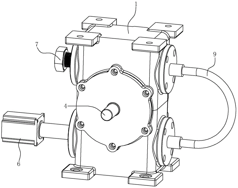
[0031] Such as Figure 1~4 Shown is the first preferred embodiment of the present invention.

[0032] A gapless worm gear reducer, including a casing 1 and a worm gear transmission structure arranged in the casing 1. There is one worm wheel 2 in the worm gear transmission structure, which is installed on the power output shaft 4, and the power output shaft 4 extends out of the casing 1 front end face; there are two worms in the worm gear transmission structure, which are the first worm 3 and the second worm 5 respectively, the first worm 3 and the second worm 5 are arranged in parallel and spaced up and down and are simultaneously engaged with the worm gear 2; Wherein, the first worm 3 is connected to the first motor 6 as a power input worm, and the left end of the second worm 5 is used as an adjustment end to cooperate with the gap adjustmen...


PUM


Abstract

The invention relates to a gapless worm gear worm rod speed reducer comprising a housing and a worm gear worm rod transmission structure arranged in the housing; the features are that one worm gear is arranged on a power output shaft extending outside a front end face of the housing; two worm rods comprising a first worm rod and a second worm rod arranged in parallel up and down at an interval, and the two worm rods are engaged with the worm gear; the first worm rod is in transmission connection with the a first motor so as to serve as a power input worm rod; the left end of the second worm rod serves as an adjusting end and so as to be matched with a gap adjusting part on the left side of the housing, thus finally driving the second worm rod to slide in an axial direction; the first worm rod and the second worm rod are connected through a synchronization transmission composition ensuring the first and second worm rod to make synchronization reverse rotation. The speed reducer is simple in structure, gapless, high in precision, low in production cost, can be produced by a conventional normal worm gear worm rod speed reducer production line, production technology is almost same, so no repeat investment is needed.

Description

technical field [0001] The present invention relates to a deceleration mechanism used on mechanical equipment, in particular to a worm gear reducer without clearance. CNC machine tools and other high-end CNC fields. Background technique [0002] Worm gear reducers are widely used in various processing machinery and numerical control equipment. The worm gear reducers used in known numerical control equipment often use a structure in which a worm and a worm gear cooperate, and the pitch between the worm and the worm gear is not adjustable. Due to manufacturing and assembly errors, generally there will be a certain pitch difference between the worm and the worm wheel, that is, there is a certain backlash, which has a great impact on the machining accuracy of the workpiece. Due to the existence of the backlash, when the output shaft is subjected to When the opposite tangential force occurs, jumping will occur, which will affect the accuracy of the instantaneous transmission. Th...

Claims


Application Information

Patent Timeline
Patent Type & Authority Applications(China)
IPC IPC(8): F16H1/24F16H57/12
CPCF16H1/24F16H57/12
Inventor 王烽
Owner 杭州方缘传动机械有限公司
Why Eureka
Try Eureka