
Method for reducing sludge and recycling sludge in UASB (upflow anaerobic sludge blanket) system and sludge treatment system

A sewage treatment system and sludge reduction technology, applied in water/sludge/sewage treatment, sludge treatment, sludge treatment, etc., can solve the problems of loss of granular sludge, poor effluent quality, poor sedimentation, etc. Achieve the effect of reducing nitrogen and phosphorus consumption, improving treatment rate and reducing energy consumption

Inactive Publication Date: 2015-09-30
CHINA UNION ENG
View PDF2 Cites 1 Cited by
  • Summary
  • Abstract
  • Description
  • Claims
  • Application Information

AI Technical Summary

Problems solved by technology

To improve the treatment efficiency of UASB, sufficient microorganisms with good performance are needed. The formation of granular sludge in the UASB reactor is a sign of successful domestication and operation of the system, which can allow higher volumetric loads and hydraulic loads, while granular sludge The formation time of the UASB system is relatively long. At present, the UASB system is generally mostly flocculent sludge. Because of its poor settling property, it will flow out with the overflow of the effluent, resulting in poor effluent quality. At the same time, the sludge concentration in the UASB system will be reduced. Granular sludge, due to the low sludge production of anaerobic itself, when encountering the impact of industrial wastewater water quality and water volume fluctuations, a part of the granular sludge will also be lost, which requires irregular supplementary sludge, and the market is very It is difficult to find a suitable mud source, and different mud sources also require a long period of domestication

Method used


Image

  • Method for reducing sludge and recycling sludge in UASB (upflow anaerobic sludge blanket) system and sludge treatment system

Examples


Embodiment 1

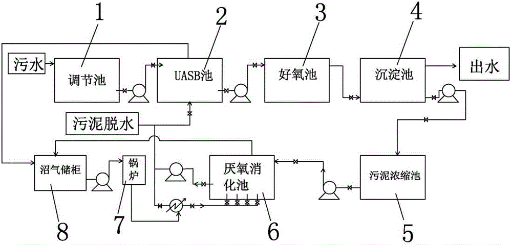
[0022] Example 1: The wastewater treatment capacity of a chemical enterprise is 2wt / d, and the sludge treatment system with sludge reduction and reuse functions according to the present invention is constructed by rebuilding the old device. The amount of digested sludge that can be obtained in one month is 662m 3 , the sludge concentration is 30000mg / L, then 19.86t of sludge (calculated as dry sludge) is replenished to the UASB pool every month to supplement the flocculent sludge lost by UASB and provide a sludge source for sludge granulation. The cost of purchasing mud sources. After analyzing the water quality of the sludge supernatant, the COD, NH3-N, TN, and TP of the concentrated sludge before digestion were 183, 0.2, 0.52, and 2.5 mg / L, respectively. TP were 969, 3.7, 10.66, and 4.8 mg / L, respectively. It can be seen that during the anaerobic digestion process of sludge microorganisms, extracellular polymer (EPS) was dissociated and released, cells entered endogenous re...


PUM


Abstract

The invention discloses a method for reducing and recycling sludge, which is characterized by comprising the following steps: 1. periodically discharging surplus sludge in a precipitation tank to a sludge concentration tank, and carrying out sludge concentration; 2. periodically extracting the sludge in the sludge concentration tank to an anaerobic digestion tank, and carrying out anaerobic mesophilic digestion; and 3. periodically sucking the anaerobic sludge acclimatized by the anaerobic digestion tank into a UASB (upflow anaerobic sludge blanket) tank as a supplemented sludge source, and dehydrating and discharging the rest digested sludge. The invention also discloses a sludge treatment system with sludge reduction and recycling functions. The method can reduce the sludge by 30-50%, reduces the discharge amount of the surplus sludge, lowers the sludge treatment cost, protects the surrounding environment, is beneficial to enhancing the treatment rate of the UASB tank, lowers the energy consumption of the aerobic unit, is especially suitable for low-nitrogen / phosphorus-content sewage which can not satisfy the biochemical requirements and needs to add additional nitrogen and phosphorus, can reduce the nitrogen / phosphorus consumption of the sewage plant, and can discharge stable water after reaching the standard.

Description

technical field [0001] The invention relates to the field of sewage treatment, in particular to a method for reducing the amount of sludge and reusing it for UASB as a supplementary sludge source and a related sludge treatment system. Background technique [0002] According to statistics, the national urban sewage treatment volume reached 34.3 billion cubic meters by the end of 2010, and the dewatered sludge production volume was close to 22 million tons. At present, the proportion of different ways of final disposal of dewatered sludge in my country is: landfill accounts for 60%-65%, aerobic fermentation of sludge for agriculture accounts for about 10%-15%, and comprehensive utilization of sludge natural drying accounts for 4%- 6%, sludge incineration accounts for 2%-3%, sludge open-air stacking and outbound transportation account for 15%-20%. Among them, most of the sludge in landfill, open storage and outbound transportation in my country is disposed of at will, which mea...

Claims


Application Information

Patent Timeline
Patent Type & Authority Applications(China)
IPC IPC(8): C02F11/00C02F11/04
CPCY02E50/30Y02W10/20
Inventor 李红周锋
Owner CHINA UNION ENG
Learn More