Eureka AIR delivers breakthrough ideas for toughest innovation challenges, trusted by R&D personnel around the world.

Solid material grinding method and solid material grinding machine

A technology of solid material and grinding method, applied in the direction of grain processing, etc., can solve the problems of ineffective collection power of fine powder, short service life of wearing parts and wear parts, and unsatisfactory separation effect of collection system. The fine powder collection effect is good, the overhaul and maintenance are simple, and the grinding particle size is fine.

Active Publication Date: 2015-09-30
蔡昌荣
View PDF6 Cites 6 Cited by
  • Summary
  • Abstract
  • Description
  • Claims
  • Application Information

AI Technical Summary

Problems solved by technology

[0004] At present, the most commonly used mills in China are Raymond mills and vertical mills, but they have the following problems in the process of use: 1) The product fineness is low, and the fineness of ordinary Raymond mills is generally below 500 mesh ; 2) High mechanical failure rate, high power consumption, high noise, and large emission pollution; 3) Low system efficiency, unsatisfactory separation effect of the product collection system, a large amount of fine powder cannot be effectively collected and repeated circulation in the system Cause power waste; 4) The larger particles in the material entering the grinding area and the particles that will not be ground in the future are often thrown into the bellows box and gathered at the tail of the volute box, and continue to extend forward, so that the air volume is gradually reduced, which is easy to cause traffic jams. Powder output or less powder output will affect the output; 5) Overhaul and maintenance are inconvenient, the service life of wearing parts and wear-resistant parts is short, and the replacement cost is high

Method used

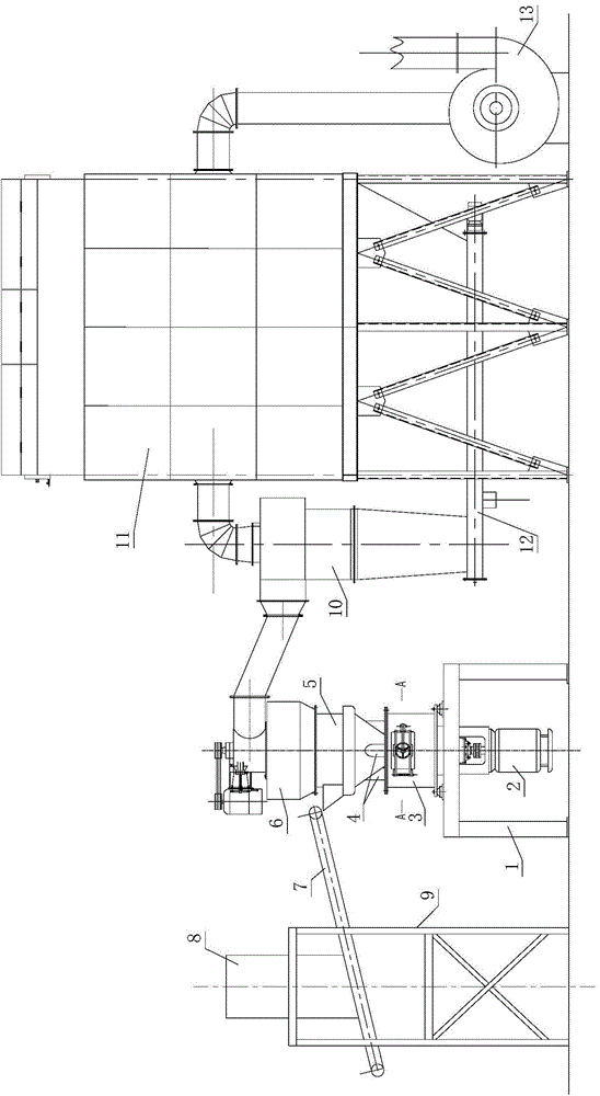
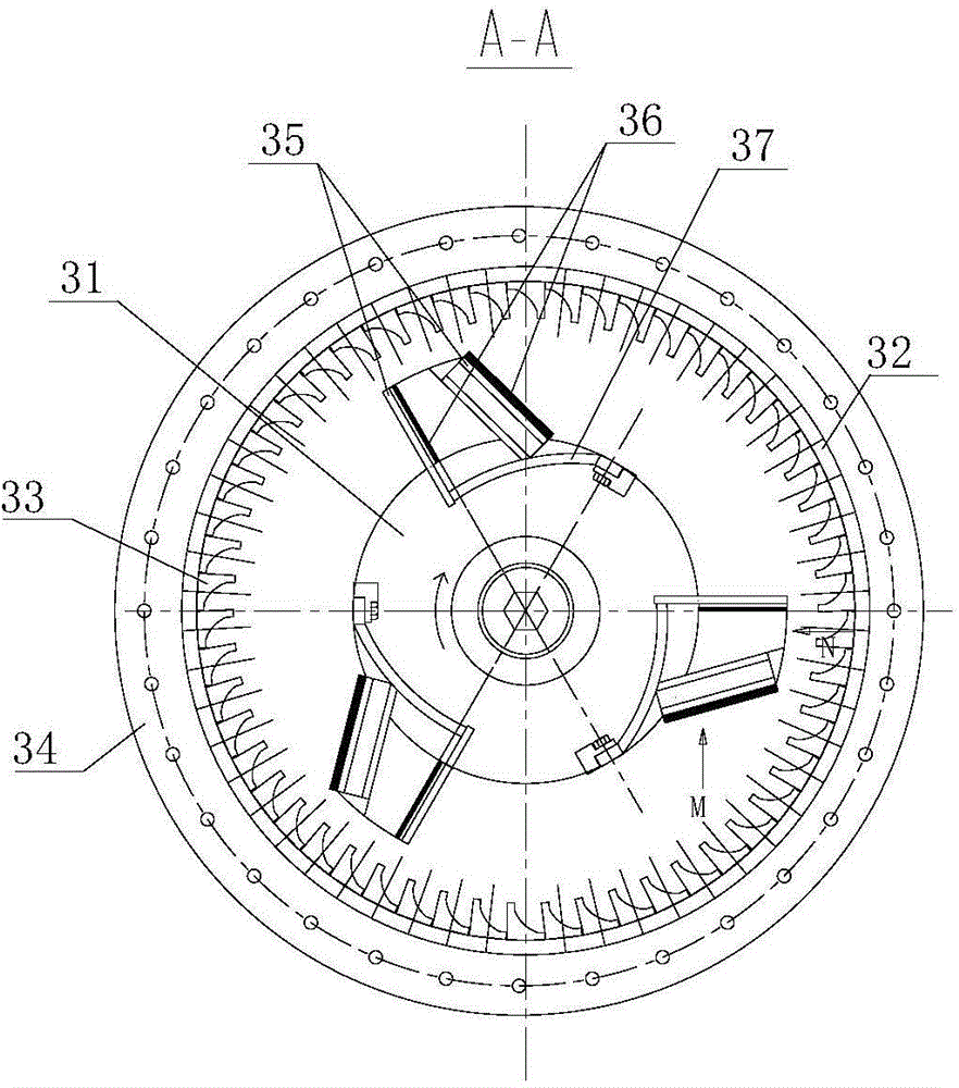
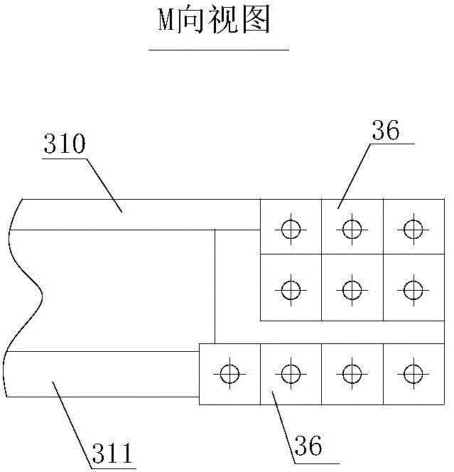

Image

  • Solid material grinding method and solid material grinding machine
  • Solid material grinding method and solid material grinding machine
  • Solid material grinding method and solid material grinding machine

Examples


Embodiment 1

[0058] The ground material is talc slag, and the specific process parameters are shown in Table 1;

[0059] Table 1

[0060] Analyzer speed

Embodiment 2

[0062] The grinding material is fused magnesium, and the specific process parameters are shown in Table 2;

[0063] Table 2

[0064] Analyzer speed

Embodiment 3

[0066] The ground material is sintered magnesia, and the specific process parameters are shown in Table 3;

[0067] table 3

[0068] Analyzer speed

[0069] In the above three embodiments, the pass rates of all finished products all reach more than 95%.


PUM


Abstract

The invention relates to a solid material grinding method and a grinding machine. Solid materials enter a grinding body of a grinding room after being subjected to primary air classification, and are thrown onto a lining plate along the radial direction to be broken due to collision under the centrifugal effect of the grinding body in high-speed rotation; after rebounding from the lining plate, the broken materials oppositely collide newly-added materials to be broken; large-particle materials drop under the gravity effect and upwards enter a working cabin through a guide pipe after being subjected to high-speed hammering; the working bin has the functions of feeding and wind mixing elutriation; the materials subjected to wind mixing elutriation enter a classifier to be classified; finished material products achieving the granularity requirements are collected by a spiral collector and a bag-type dust remover and then are discharged from a finished product discharging device; and materials not achieving the granularity requirements are returned to the grinding room to be reground. The grinding machine has the beneficial effects that the grinding granularity is small, the grinding efficiency is high, the fine powder collecting effect is good, the equipment is compact in structure, the maintenance cost is low, powder bodies with the granularity in a range of 80-1,500 meshes can be produced, and the grinding machine has the advantages of high yield ad stable quality particularly when producing ultrafine powder with the granularity being greater than 800 meshes and materials with higher rigidity.

Description

technical field [0001] The invention relates to the technical field of solid material crushing, in particular to a solid material grinding method and a solid material grinding machine for finished material whose particle size ranges from 80 to 1500 mesh. Background technique [0002] The superfine pulverization technology of pulverizer is a new pulverization engineering technology developed along with modern high technology and new material industry in recent years, and has become one of the most important deep processing technologies of industrial minerals and other raw materials. The development of high-tech industries is of great significance. After the material is ultra-fine, with the increase of its surface area, other performance changes can be caused, and the use effect and utilization rate of the material can be greatly improved. Ultrafine powder is infiltrating the entire industrial sector and high-tech fields, and is known as the origin of modern high-tech. Ultra...

Claims


Application Information

Patent Timeline
IPC IPC(8): B02C21/00B02C13/18B02C13/288B02C13/282B02C23/18
CPCB02C13/1807B02C13/282B02C13/288B02C21/00B02C23/18
Inventor 蔡昌荣曹星
Owner 蔡昌荣
Why Eureka
Eureka Blog
Learn More