
Method and device for acquiring location information of gamma photons in PET equipment

A position information and gamma photon technology, applied in the field of electronic information, can solve the problem of inaccurate acquisition of position information, and achieve the effect of improving accuracy and precise sampling

Inactive Publication Date: 2015-09-23
NEUSOFT MEDICAL SYST CO LTD
View PDF3 Cites 7 Cited by
  • Summary
  • Abstract
  • Description
  • Claims
  • Application Information

AI Technical Summary

Problems solved by technology

[0005] In view of this, an embodiment of the present invention provides a method and device for obtaining position information of gamma photons in PET equipment, so as to solve the technical problem of inaccurate position information acquisition in the prior art

Method used


Image

  • Method and device for acquiring location information of gamma photons in PET equipment
  • Method and device for acquiring location information of gamma photons in PET equipment
  • Method and device for acquiring location information of gamma photons in PET equipment

Examples


Embodiment 1

[0051] see Figure 4 As shown, the first embodiment of the method for obtaining the position information of the gamma photon in the PET device provided in the embodiment of the present invention may include the following steps:

[0052] Step 401: Receive four channels of photomultiplier tube PMT signals collected by the detector module in the PET device, and superimpose all PMT signals and two adjacent PMT signals respectively.

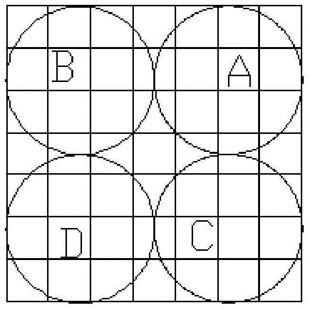
[0053] For example, see figure 1 As shown in the schematic diagram of the detector module, the photomultiplier tube A can collect the first PMT signal Ea, the photomultiplier tube B can collect the second PMT signal Eb, the photomultiplier tube C can collect the third PMT signal Ec, and the photomultiplier tube D can acquire the fourth PMT signal Ed.

[0054] Because a single PMT signal output is a series of waveforms with different amplitudes, it cannot be guaranteed that the data can be obtained when the PMT signal amplitude is very small. superp...

Embodiment 2

[0066] see Figure 5 As shown, the second embodiment of the method for obtaining the position information of the gamma photon in the PET device provided in the embodiment of the present invention may include the following steps:

[0067] Step 501: Receive the four-way photomultiplier tube PMT signals Ea, Eb, Ec, Ed corresponding to the γ photons collected by the detector module in the PET device.

[0068] For example, see figure 1 As shown in the schematic diagram of the detector module, the photomultiplier tube A can collect the first PMT signal Ea, the photomultiplier tube B can collect the second PMT signal Eb, the photomultiplier tube C can collect the third PMT signal Ec, and the photomultiplier tube D can acquire the fourth PMT signal Ed.

[0069] Step 502: Superimpose the PMT signal to obtain a first superimposed signal Eab, a second superimposed signal Ecd, a third superimposed signal Eac, a fourth superimposed signal Ebd, and a fifth superimposed signal E.

[0070]...


PUM


Abstract

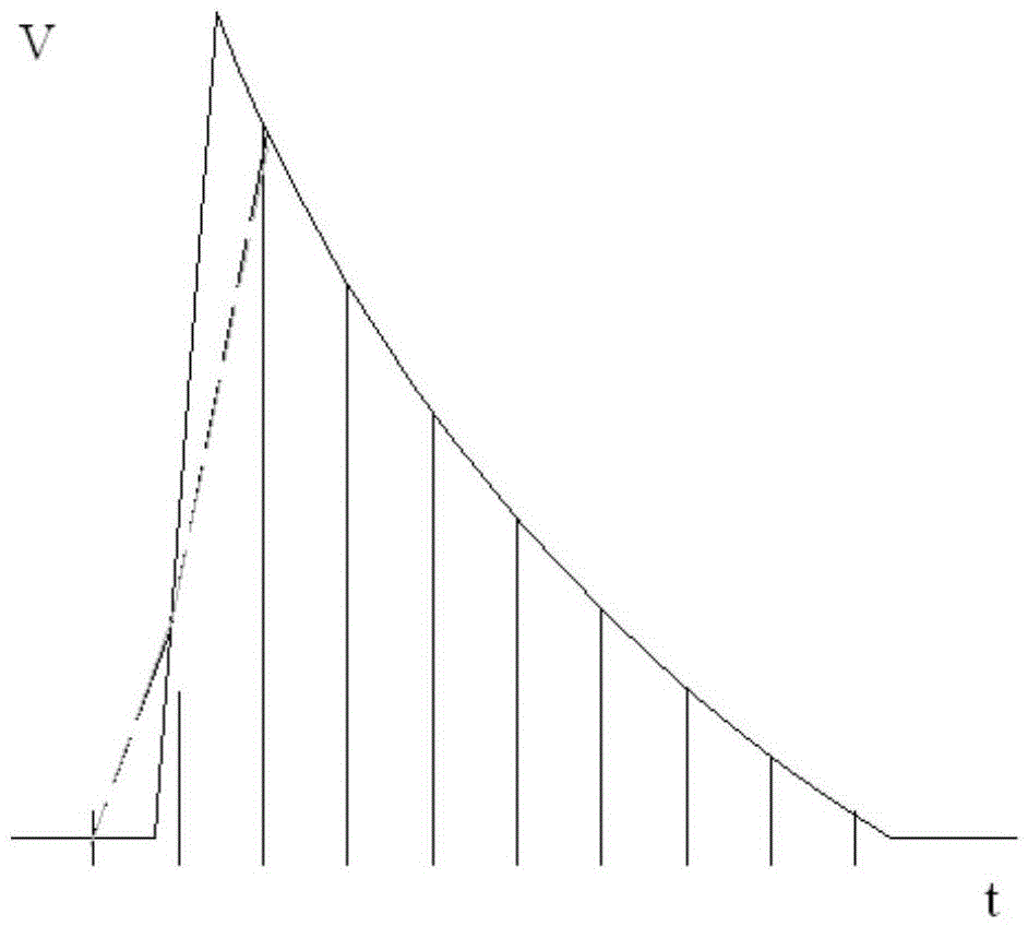
The invention discloses a method and a device for acquiring the location information of gamma photons in PET equipment, which is used for accurately acquiring the location information of gamma photons. The method comprises the steps of receiving four paths of PMT signals Ea, Eb, Ec and Ed acquired by a detector module; superposing the signals to acquire superposed signals Eab, Ecd, Eac, Ebd and E; selecting one path of superposed signals from Eab and Ecd, and from Eac and Ebd respectively, according to the selecting condition that the maximal amplitude of the superposed signals is larger than or equal to a first amplitude; marking the sampling time for the selected superposed signals and the rising edge of E when passing through the sampling points of a second amplitude and a third amplitude, sampling the selected superposed signals and the falling edge of E, fitting the waveform of the selected superposed signals and the waveform of E; and acquiring the location information of gamma photons according to the sampled waveform of the selected superposed signals and the sampled waveform of E.

Description

technical field [0001] The invention relates to the field of electronic information, in particular to a method and device for acquiring gamma photon position information in PET equipment. Background technique [0002] PET (Positron Emission Tomograph, Positron Emission Computed Tomography) system is an advanced molecular imaging device. Some tracers containing positron nuclides will release positron e+ during the decay process, and the released positron e+ will annihilate with negative electron e- in the surrounding environment after moving for a certain distance in the human body, resulting in A pair of gamma photons with equal energy (511KeV) and opposite propagation directions (about 180 degrees). Using the detection equipment of the PET system, the gamma photon pairs can be detected, and then the existence of positrons can be analyzed to obtain the concentration distribution of the tracer in the subject's body. [0003] The detection equipment of the PET system general...

Claims


Application Information

Patent Timeline
IPC IPC(8): G01T1/202
Inventor 赵玉秋张国旭王治国杨龙高鹏
Owner NEUSOFT MEDICAL SYST CO LTD
Learn More