
Liquid exhaust pipe purifier

A technology for exhaust pipes and purifiers, applied in the field of purifiers, which can solve the problems of shortening the service life of exhaust pipes, aggravating the aging of catalysts, and reducing catalytic efficiency, etc., and achieve the effects of prolonging service life, exquisite structure, and reducing high-temperature damage

Active Publication Date: 2015-09-23
南通中智检测服务有限公司
View PDF5 Cites 3 Cited by
  • Summary
  • Abstract
  • Description
  • Claims
  • Application Information

AI Technical Summary

Problems solved by technology

[0002] The purification devices commonly used in automobile exhaust systems mainly include three-way catalytic converters. Its carrier part is a porous ceramic material, and precious metals such as platinum, rhodium, and palladium are coated on its surface; CO, HC and NO in exhaust gas X and other harmful gases are decomposed into CO 2 、H 2 O, N 2 and O 2 and other harmless gases and discharged into the air; this kind of purifier has the following disadvantages: First, it needs to ensure a certain active temperature during use; when the temperature is too low, the catalytic efficiency drops sharply, and when the temperature is too high, it is easy to cause The aging of the catalyst is aggravated, which shortens the service life of the purifier; second, the cost of this purifier is relatively high; third, since the active temperature is between 400°C and 800°C, the temperature of the gas discharged from the purifier is high, which will accelerate the installation of the purifier The aging of the muffler at the rear shortens the service life of the entire exhaust pipe

Method used


Image

  • Liquid exhaust pipe purifier

Examples


Embodiment

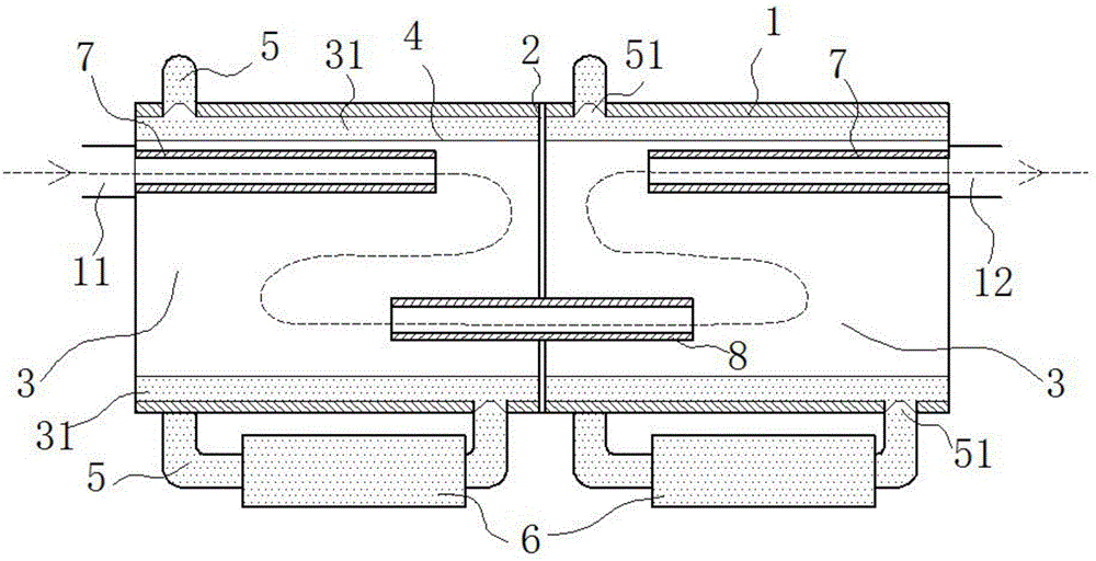
[0013] exist figure 1 In the shown embodiment, the liquid exhaust pipe purifier includes an air inlet 11, an air outlet 12 and a cylindrical shell 1, the outer wall of the shell 1 is coated with an insulating layer; the shell The body 1 is divided into two closed expansion chambers 3 by an insulating partition 2 perpendicular to the axis of the housing 1; Elastic net tube 4, the mesh aperture of the net tube 4 reaches the level of liquid seal; in the airtight purification ring tube surrounded by the shell 1, the partition plate 2 and each of the net tubes 4 31 is filled with purification liquid; each of the purification ring cylinders 31 is connected to the elastic cooling box 6 made of transparent material through two liquid guide tubes 5 locked by a one-way valve 51, each of the purification ring cylinders 31 and each The elastic cooling box 6 forms a sealed circuit through the guide pipe 5; metal guides parallel to the axis of the housing 1 and extending toward the inside ...


PUM


Abstract

The invention relates to a liquid exhaust pipe purifier. A shell is divided by an insulating partition plate perpendicular to the axis of the shell into two closed expansion cavities. An elastic net cylinder parallel to and coaxial with the shell is installed in each expansion cavity. Closed purification ring cylinders defined by the shell, the partition plate and the net cylinders are filled with purification liquid. The purification ring cylinders are communicated with elastic cooling boxes, metal gas guide pipes are fixed to the gas inflow end and the gas outflow end respectively, a metal ventilation pipe perpendicularly penetrating through the partition plate is fixed to the partition plate, the metal gas guide pipes and the metal ventilation pipe are electrically connected with the positive electrode of a high-voltage power source, and the shell is electrically connected with the negative electrode of the high-voltage power source. The purifier is low in manufacturing cost and small in size, harmful gas and impurities in tail gas can be efficiently purified, the auxiliary silencing function is achieved, the temperature of the tail gas can be reduced, and the service life of an exhaust pipe is prolonged.

Description

technical field [0001] The invention relates to an automobile exhaust pipe fitting, in particular to a purifier. Background technique [0002] The purification devices commonly used in automobile exhaust systems mainly include three-way catalytic converters. Its carrier part is a porous ceramic material, and precious metals such as platinum, rhodium, and palladium are coated on its surface; CO, HC and NO in exhaust gas X and other harmful gases are decomposed into CO 2 、H 2 O, N 2 and O 2 and other harmless gases and discharged into the air; this kind of purifier has the following disadvantages: First, it needs to ensure a certain active temperature during use; when the temperature is too low, the catalytic efficiency drops sharply, and when the temperature is too high, it is easy to cause The aging of the catalyst is aggravated, which shortens the service life of the purifier; second, the cost of this purifier is relatively high; third, since the active temperature is ...

Claims


Application Information

Patent Timeline
IPC IPC(8): F01N3/04F01N3/01F01N1/06
Inventor 陈伟强
Owner 南通中智检测服务有限公司
Learn More