Combined catalyst stripper

A stripper and stripping technology, applied in catalyst regeneration/reactivation, physical/chemical process catalysts, catalytic cracking, etc., can solve the problems of inability to separate catalysts, reduce stripping mass transfer efficiency, etc., and prevent catalyst backmixing Effect

Inactive Publication Date: 2015-09-23
QINGDAO JINGRUN PETROCHEM ENG
View PDF5 Cites 0 Cited by
  • Summary
  • Abstract
  • Description
  • Claims
  • Application Information

AI Technical Summary

Problems solved by technology

The upper and lower sides of the baffle or grille are catalysts in the state of dense-phase fluidized bed. The baffle or grille is only a component placed in the dense-phase fluidized bed, which cannot separate the catalyst on the upper and lower sides of the baffle or grille, so that the stripping A "backmix" state is formed in the device
This working condition is the same as the "liquid flooded column" working condition in the rectification column, which greatly reduces the efficiency of stripping and mass transfer

Method used


Image

  • Combined catalyst stripper
  • Combined catalyst stripper
  • Combined catalyst stripper

Examples


Embodiment

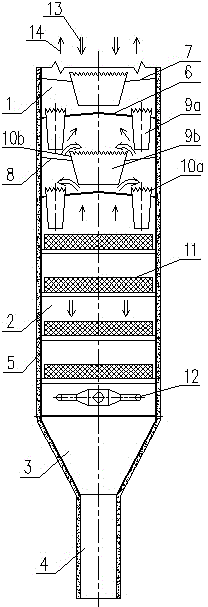
[0026] Example: The amount of catalyst to be stripped is 1000t / h, the temperature is 500°C, the average particle diameter of the catalyst is 50 μm, the particle density of the catalyst is 850kg / m3, the stripping medium is steam, and the steam temperature is 400°C.

[0027] Stripper of the present invention sees figure 1 .

[0028]The diameter of the stripper is 3000mm, and the height is 9500mm. There are 4 layers of stripping plates in the plate stripping area, and the distance between the stripping plates is 1000mm; The angle α between the surface radial line and the horizontal line is 5°. The first layer of stripping plate is equipped with a catalyst downcomer. The height of the overflow weir H1 is 150mm. The catalyst downcomer is a positive cone (θ is zero degree), and the upper inlet diameter is 1300mm, the diameter of the lower outlet is 1100mm, the distance H3 between the outlet of the catalyst downcomer and the lower stripping plate is 200mm; The angle α with the hori...


PUM

PropertyMeasurementUnit
pore sizeaaaaaaaaaa
widthaaaaaaaaaa
lengthaaaaaaaaaa

Abstract

The invention discloses a stripper for a combined catalyst or other solid particles, and belongs to the field of gas-solid catalytic reaction. The combined catalyst stripper consists of a plate type overflow stripping region without backmixing at the upper part and a dense-phase grating stripping region at the lower part, wherein stripping gas raising hole plates, catalyst overflow weirs and catalyst descending channels are arranged on an overflow stripping plate; the cross section of the stripper is divided into many channels communicated from top to bottom through gratings in the grating stripping region, so that the high-efficiency contact between a gas phase and a solid phase can be realized, the free flow and the free exchange of the catalyst and stripping gas are realized, and the enough contact time of the catalyst and the stripping gas can also be ensured. The combined catalyst stripper disclosed by the invention is suitable for stripping various catalyst entraining reaction products and various entrainment impurities in the catalytic conversion technology.

Description

technical field [0001] The invention belongs to the field of petrochemical industry and relates to a combined catalyst stripping equipment, in particular to a combined equipment for stripping oil gas or other media entrained and adsorbed in the catalyst. Background technique [0002] In the settler of the catalytic conversion device, when the reaction is over, the catalyst after gas-solid separation still entrains some oil and gas, resulting in an increase in the amount of coke, energy consumption, and light oil yield. In order to strip out the oil and gas carried in the catalyst, mainly the oil and gas entrained between the catalyst particles and the oil and gas adsorbed in the catalyst pores, purify the catalyst, and control the heat of burning, we often use steam stripping to remove the oil and gas in the catalyst. Replacement, thus resulting in a catalyst stripping device - the stripper. [0003] The oil-gas displacement and desorption in the stripper is a typical gas-s...

Claims


Application Information

Patent Timeline
Patent Type & Authority Applications(China)
IPC IPC(8): C10G11/18B01J8/34B01J38/06
Inventor 石宝珍石林
Owner QINGDAO JINGRUN PETROCHEM ENG
Why Eureka
Try Eureka