
Temperature controllable electronic condensation rotary evaporator

A rotary evaporator, controllable technology, applied in the direction of distillation in rotating containers, refrigerators, sustainable buildings, etc., can solve the problem that water-cooled condensers are difficult to reach the condensation temperature, the recovery rate of low-boiling volatile solvents is low, and the distillate Can not be accurately controlled and other problems, to achieve the effect of simple structure, easy popularization and high reliability

Inactive Publication Date: 2015-09-23
李景峰 +1
View PDF5 Cites 5 Cited by
  • Summary
  • Abstract
  • Description
  • Claims
  • Application Information

AI Technical Summary

Problems solved by technology

[0005] In order to change the serious waste of water resources by traditional rotary evaporators, the invention solves the problem that its water-cooled condenser is difficult to reach the required condensation temperature, so that the recovery rate of low-boiling volatile solvents is low, resulting in waste of raw materials and environmental pollution ; For distillates with different condensation temperatures, the corresponding temperature cannot be accurately controlled; Substances with different vaporization temperatures in the reaction system cannot be condensed in stages after entering the condenser; and the built-in electronic condenser is affected by the ambient temperature and the conduction process. There are many defects such as the influence produced; provide a controllable electronic condensation rotary evaporator that can isolate the outside of the condensation tube of the rotary evaporator from the ambient temperature, increase the cooling area to improve the condensation efficiency, and adjust the condensation temperature according to different fractions

Method used


Image

  • Temperature controllable electronic condensation rotary evaporator
  • Temperature controllable electronic condensation rotary evaporator
  • Temperature controllable electronic condensation rotary evaporator

Examples


Embodiment Construction

[0026] Below in conjunction with accompanying drawing and specific embodiment the present invention is described in further detail:

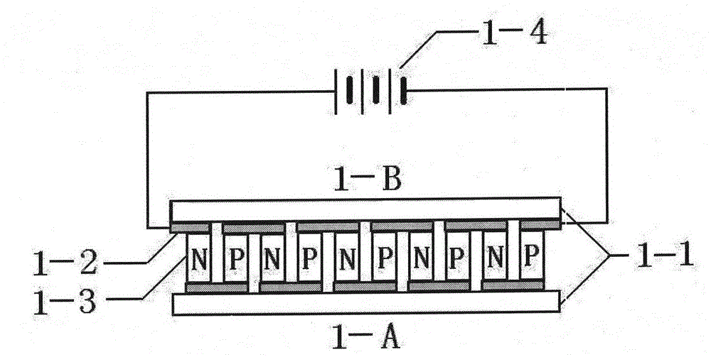
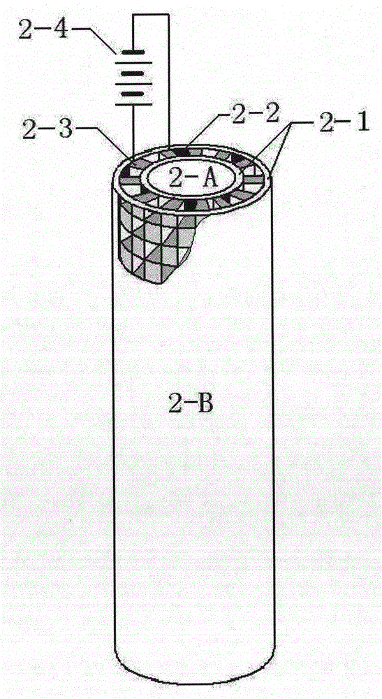
[0027] The structure and working principle of electronic refrigeration components are as follows: figure 1 , figure 2 As shown, 1-1 and 2-1 are insulating ceramics, 1-2 and 2-2 are metal conductors, 1-3 and 2-3 are N-type and P-type semiconductors, 1-4 and 2-4 are DC power supplies . After the DC power supply is connected to the electronic refrigeration element, the energy transfer will be generated immediately, and the current will flow from the N-type element to the joint of the P-type element to absorb heat, and the 1-A and 2-A surfaces will become cold junctions, and the temperature will drop; from the P-type element to the N The joints of the type components release heat, and the 1-B and 2-B surfaces become hot ends and the temperature rises. Usually, the temperature difference between the cold and hot ends of electronic refrigeration c...


PUM


Abstract

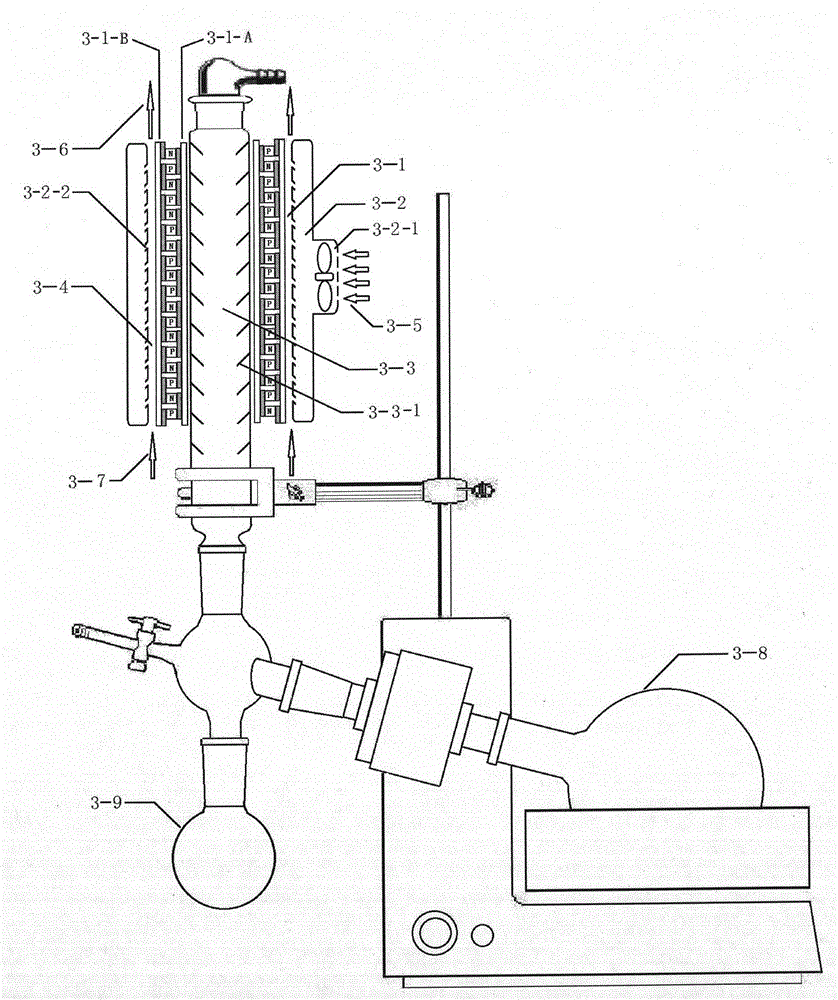
The invention discloses a temperature controllable electronic condensation rotary evaporator. The temperature controllable electronic condensation rotary evaporator mainly comprises a distillation flask, a thermostat water bath, a decompression pump, a receiving bottle and an electronic condenser. The electronic condenser comprises a cylindrical electronic refrigeration component, a cylindrical airflow heat radiator and a finned condensing pipe. During distillation, the cold end of the electronic refrigeration component absorbs heat temperature in the condensing pipe, thermal steam in the distillation flask contacts with the wall of the condensing pipe and fins to condense, heat of the hot end is guided out by the heat radiator, and the cold end of the electronic refrigeration component is always kept at low temperature. Since the condensing pipe is isolated from the environment temperature, cooling area is enlarged and condensing temperature is lower, condensing efficiency is improved. By adjusting input current of the electronic condenser, condensation temperature can be precisely controlled; a water-cooling condenser of an existing rotary evaporator can be replaced; the temperature controllable electronic condensation rotary evaporator is simple in structure, convenient to use, easy to manufacture and popularize and has great significance in environment protection and water saving.

Description

technical field [0001] The invention relates to scientific research institutes, colleges and universities, and enterprise research and development institutions in the fields of chemistry, chemical industry, pharmacy, food, environment, etc.; it specifically belongs to the field of experimental instruments and equipment technology manufacturing, and especially relates to a temperature-controllable cooling water cooling system Electronic condensation rotary evaporator. Background technique [0002] For a long time, the whole society has been vigorously advocating water conservation. Water conservation facilities in industry, agriculture, service industry, and daily life have adopted active and effective water conservation methods and means, and achieved remarkable results. However, for research institutes, school laboratories and other research and education institutions, or scientific research departments engaged in water-saving research, the waste of experimental research wa...

Claims


Application Information

Patent Timeline
IPC IPC(8): B01D3/08F25B21/00
CPCY02B30/00
Inventor 李景峰
Owner 李景峰
Learn More