
A Plasma Series Compensation Gap System

A plasma and plasma generator technology, applied in the field of ion series compensation gap system, can solve the problems of uneven voltage division between two arc starting gaps, self-triggering voltage lower than the design value, complex structure of spark gap, etc., to improve electromagnetic resistance Effects of interference, elimination of component failure rate, and simplification of structure

Active Publication Date: 2017-10-24
CHINA SOUTHERN POWER GRID EHV POWER TRANSMISSION COMPANY WUZHOU BUREAU +1
View PDF6 Cites 0 Cited by
  • Summary
  • Abstract
  • Description
  • Claims
  • Application Information

AI Technical Summary

Problems solved by technology

Due to the complex structure of the spark gap, it is greatly affected by the stray capacitance to the ground, resulting in uneven voltage division between the two arcing gaps, and the self-triggering voltage is seriously lower than the design value
The electromagnetic environment inside the interstitial room is complex, and the equipment is affected by electromagnetic interference, which leads to frequent failures

Method used


Image

  • A Plasma Series Compensation Gap System
  • A Plasma Series Compensation Gap System
  • A Plasma Series Compensation Gap System

Examples


Embodiment 1

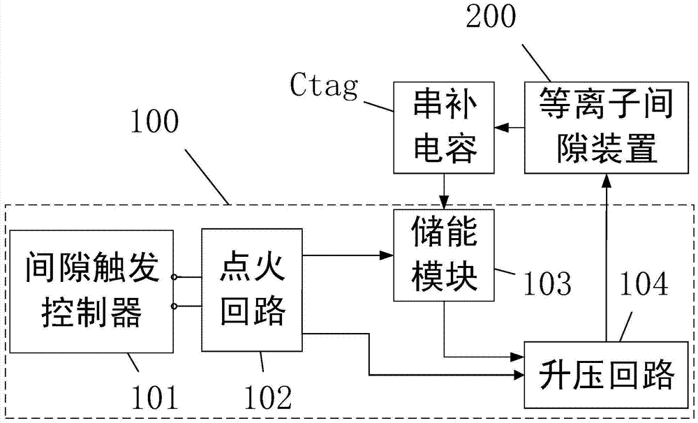
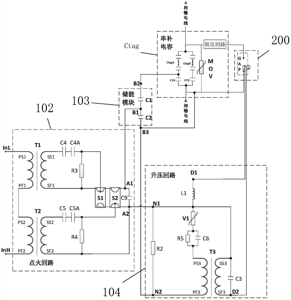
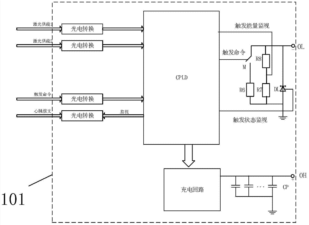
[0023] see figure 1 , is a connection block diagram of Embodiment 1 of a plasma series compensation gap system of the present invention. The plasma series compensation gap system of this embodiment is used to protect the series compensation capacitor Ctag connected in series on the three-phase line of the high-voltage transmission line, that is, every The phase line configuration has a series compensation capacitor Ctag. The series compensation capacitor Ctag includes one or two parallel capacitor banks in series. In this embodiment, two sets of capacitor banks in series are preferably used to connect a set of plasma series compensation gap systems, and the second plasma gap system is used as a backup system. The two sets of series capacitor banks are the first series capacitor bank CtagA and the second series capacitor bank CtagB, and the series compensation capacitor Ctag also includes a metal oxide voltage limiter MOV connected in parallel at both ends of the above series c...

Embodiment 2

[0052] see Figure 4 , is the connection block diagram of Embodiment 2 of the dual-ignition plasma series compensation gap system of the present invention.

[0053]Embodiment 2 of the present invention, on the basis of the gap trigger device 100 and the plasma gap device 200 of the above-mentioned embodiment 1, also includes a laser power supply device 300 and a series compensation protection device 400, and the laser power supply device 300 is used for Provide laser energy to the gap trigger controller 101. In this embodiment, two energy supply optical fibers are used as energy supply lines, and the two optical fibers are used as backups for each other to improve system reliability. As another embodiment, only One energy supply optical fiber, or two or more energy supply optical fibers, using laser energy to replace the energy supply mode of cables and inductance coils, can avoid the electromagnetic interference introduced by cables, thereby reducing the probability of damage...


PUM


Abstract

A plasma series compensation gap system of the present invention is used to protect the series compensation capacitor connected in series on the high-voltage transmission line and the metal oxide voltage limiter connected in parallel at both ends, and the plasma gap device includes a gap connected in parallel with the series compensation capacitor And a plasma generator for triggering the gap action; a gap trigger device for receiving external energy supply and gap triggering instructions, and outputting pulse voltage to the plasma generator to trigger the gap action. The gap action can be triggered by the plasma generator, which can realize the wide gap setting and effectively reduce the false triggering of the gap; and the use of multiple ignition circuits can enhance the reliability of the gap trigger; the laser energy supply method can reduce the influence of electromagnetic shielding.

Description

technical field [0001] The invention relates to the field of power transmission, in particular to a plasma series compensation gap system. Background technique [0002] The series compensation device is used on the high-voltage transmission line to improve the stable transmission capacity of the system. The series compensation device is also called series compensation. The series capacitor on the high-voltage transmission line is used to offset the influence of the line inductance, thereby improving the electrical parameters of the line and realizing the transmission of two lines. The power of the three lines not only improves the transmission power but also saves investment and maintenance costs. The gap is the core device of the series compensation, which can effectively protect the metal oxide voltage limiter (MOV) and the series compensation capacitor from overvoltage damage. [0003] There are two types of gaps for high voltage series compensation: graphite gap and pla...

Claims


Application Information

Patent Timeline
Patent Type & Authority Patents(China)
IPC IPC(8): H02H9/04
Inventor 温才权王德昌宋永佳张子敬
Owner CHINA SOUTHERN POWER GRID EHV POWER TRANSMISSION COMPANY WUZHOU BUREAU
Learn More